6.7
ENGINE
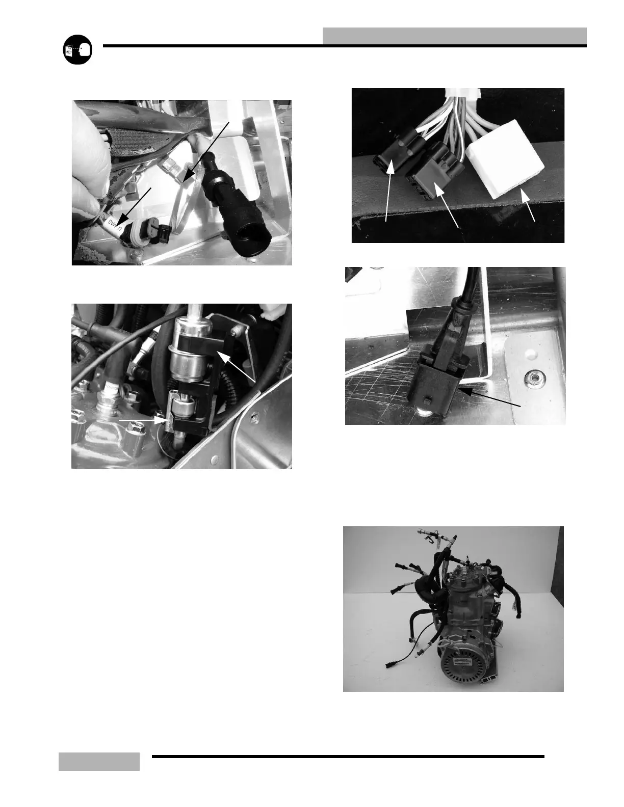
wiring harness located under the ECU area. Each injector
should be labeled.
26. Locate the fuel filter and remove the filter bracket (4), to
make room to remove the fuel line clip (5).
27. Remove the 3/8” fuel clip form the line and remove the
fuel filter. The supply line will stay with the engine.
‘FUEL CLIP REMOVAL” on page 12.3
28. Remove the fuel filter.
29. Disconnect the Regulator Rectifier (6) (yellow wires)
connector.
30. Disconnect the Stator Coil connector (7).
31. Disconnect the Crank Position Sensor connector (8).
32. Disconnect the DET sensor harness (9).
33. Route these connections through the chassis so that they
can come out with the engine.
34. Tilt the engine forward and route the rear cooling hoses, oil
lines, fuel lines and wiring so that the engine can be
removed.
35. Tilt the engine back and remove the two fasteners that hold
the front engine mount plate in the chassis.
36. Have an engine lift, lifting with slight pressure on the
engine and pull the engine forward to gain access to the
Injector Connection
2
3
4
5
6
7
8
9
 Loading...