11.22
REAR SUSPENSION
WALKER EVANS SHOCK VALVE PART
NUMBERS
SHOCK VALVING ARRANGEMENT
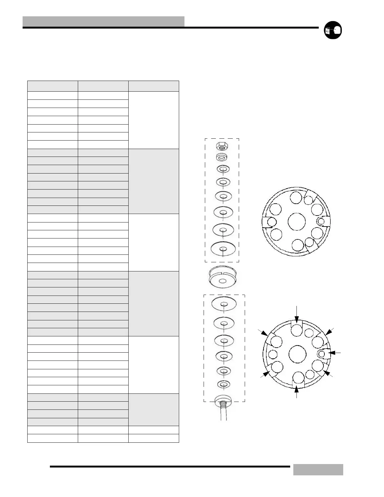
Shown below is an example of how valving stacks are
arranged. The Production Shock Information contain
production valving specifications and piston orifice sizes.
Parts in the box below are an example of standard valving.
NOTE: Note the direction of the valve piston before
disassembly. The side with the greater number of
relief slots (1) should face the nut end (2) of the
shaft.
Table 11-23:
PART NUMBER SIZE THICKNESS
1800051 .700
.006
1800075 .800
1800076 .900
1800077 1.000
1800078 1.100
1800079 1.200
1800080 1.300
1800081 .700
.008
1800082 .800
1800083 .900
1800084 1.000
1800085 1.100
1800086 1.200
1800087 1.250
1800088 1.300
1800052 .700
.010
1800053 .800
1800054 .900
1800055 1.000
1800056 1.100
1800057 1.200
1800058 1.300
1800059 .700
.012
1800060 .800
1800061 .900
1800062 1.000
1800063 1.100
1800064 1.200
1800089 1.250
1800072 1.300
1800066 .700
.015
1800067 .800
1800068 .900
1800069 1.000
1800070 1.100
1800071 1.250
1800072 1.300
1800090 1.000
.025
1800091 1.100
1800092 1.200
1800093 1.300
1800050 .625 .065
1800204 .875 .090
 Loading...