13.24
ELECTRICAL
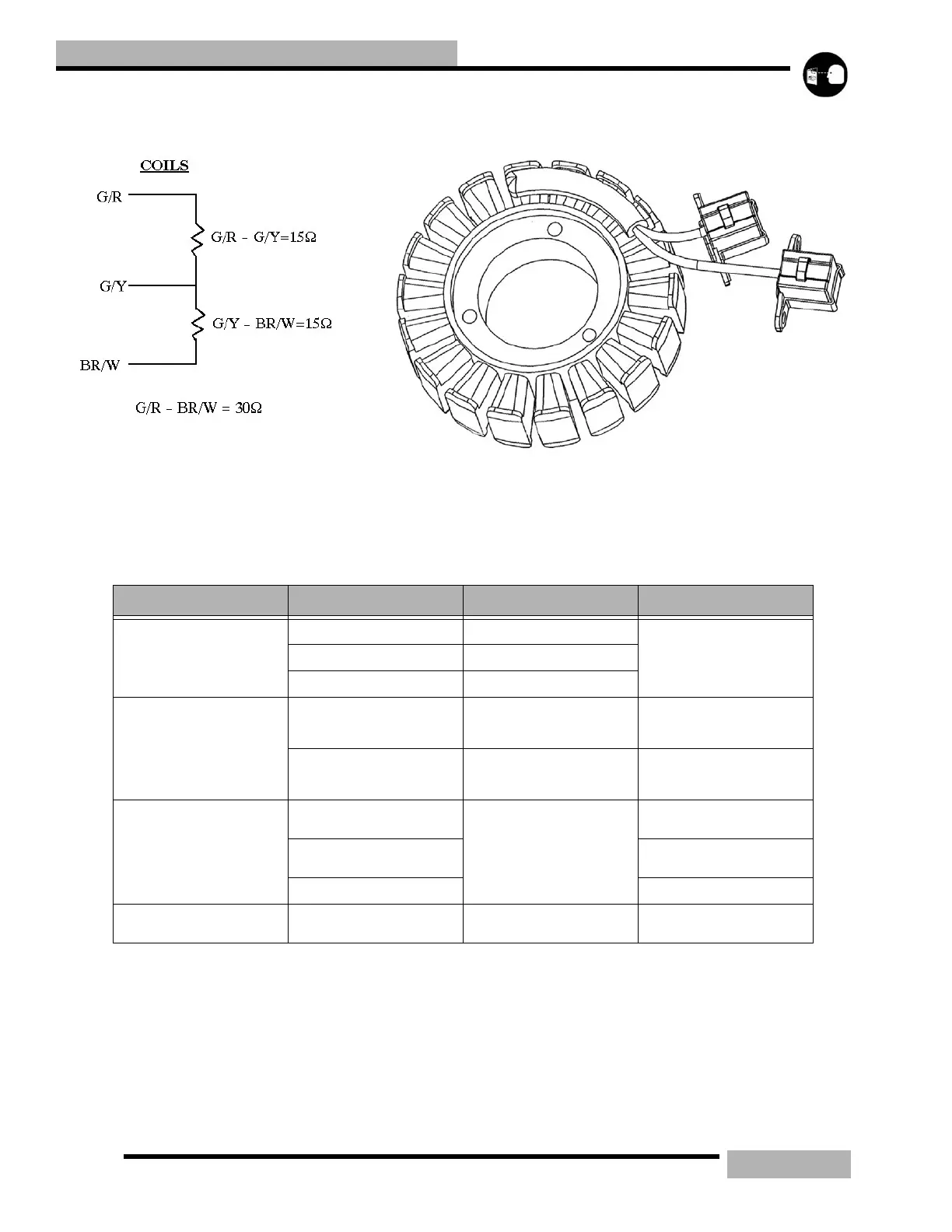
STATOR
The stator supplies the system with 3 Phase AC current to
power the electrical system 300 watts.
If the gauge and lights cut out above 3500 RPM the charge
coils are suspect to failure. When the brown/white wire is
disconnected it will have no continuity to ground.
Table 13-18:
ITEM COLOR SYSTEM FUNCTION VALUE
CHARGE
YELLOW Charge coil
Resistance between the coils =.13W
+15%
No continuity between any Yellow
to ground
YELLOW Charge coil
YELLOW Charge coil
CRANK POSITION SENSOR
(CPS)
GRN/GRN WHITE
Crank Position Sensor (5 Tooth)
Ignition timing. machine will not
run with out.
Resistance between and Green/
Green White 190 W+15%
RED/RED WHITE
Crank Position Sensor (2 Tooth)
Locates TDC and RPM. Machine
will not run with out.
Resistance between White/Red and
White = 190 W+15%
COILS
Green/Red
Exciter Coil - Powers the Ignition
Coils
Resistance between Green/Red and
Green/Yellow = 15W
Green/Yellow
Resistance between Green/Red and
Brown/White = 30W
Brown/White Ground
INJECTORS Blue/Yellow
Injector Coil - Powers Injectors to
16 Volts
Resistance between Blue/Yellow
and Blue/Yellow - 2.4W
 Loading...