5
9929422 R02 - 2017-2019 ACE 900 Service Manual
© Copyright Polaris Industries Inc.
5.21
7. Apply 0.1mL of Loctite® 620™ and 0.1mL of Loctite®
7088™ Primer in 90° apart to the threads of the
spider jamb nut. Install spider jamb nut onto
stationary shaft threads.
8. Tighten the spider jam
a
nut using Clutch Spider Nut
Socket (PU-50578). Torque jam nut to specification.
TORQUE
Spider Jamb Nut:
250 ft-lb (339 Nm) (Apply 0.1 mL Loctite® 620™)
90° apart to the threads of the spider jam nut.
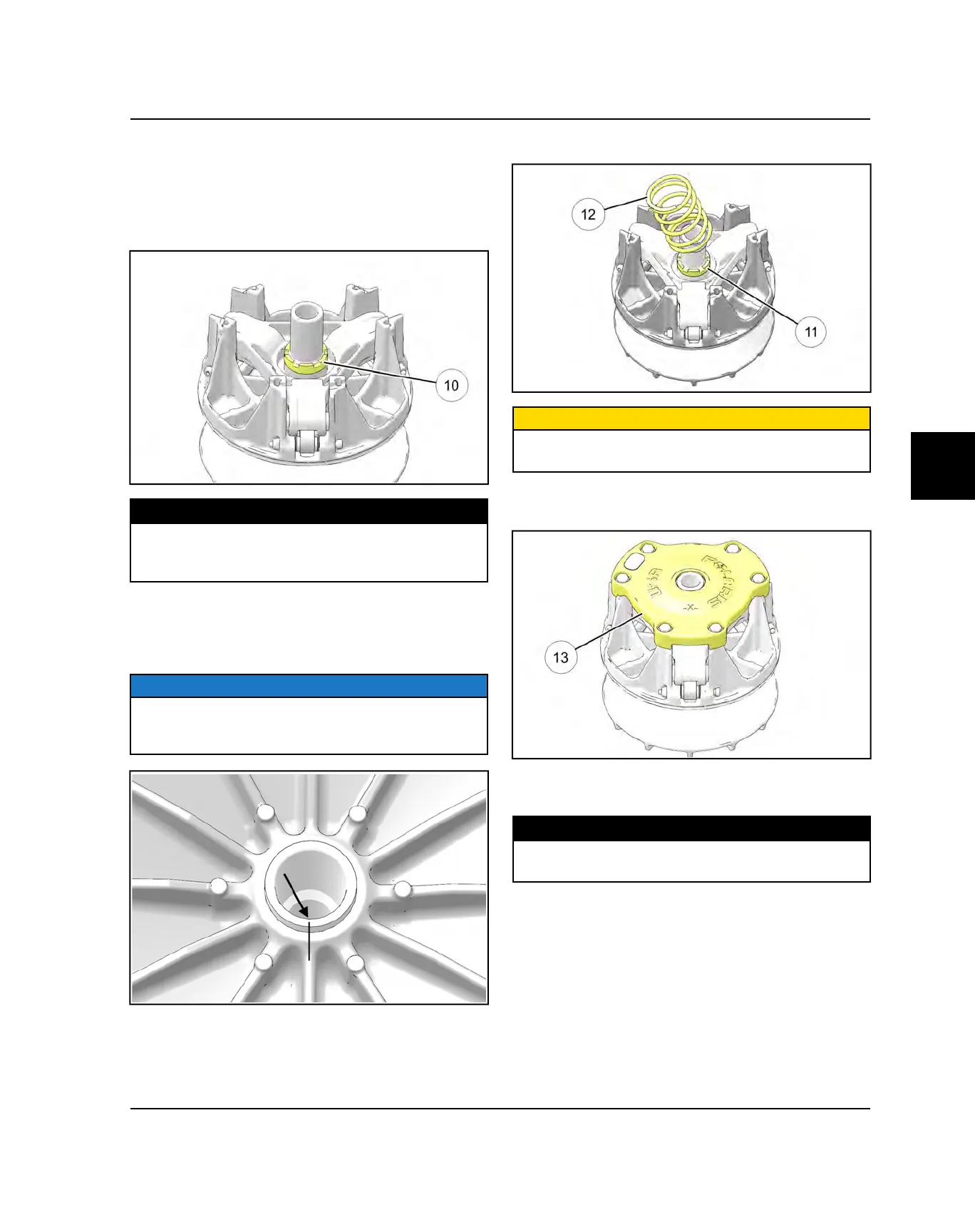
9. After the spider and jamb nut have been torqued,
remove the clutch assembly from the holding fixture
and inspect the alignment marks made during
disassembly.
NOTICE
If the marks illustrated below are not in alignment upon
assembly, the clutch will not be in balance and the drive
clutch assembly must be replaced.
10.Install the limiter spacer
s
and the clutch spring
d
.
CAUTION
DO NOT reassemble the drive clutch without the limiter
spacer. Belt life will be greatly reduced.
11. Install the drive clutch cover
f
. Be sure all alignment
marts are in alignment.
12.Install cover bolts and torque in a cross pattern
evenly to specification.
TORQUE
Drive Clutch Cover Bolts:
8 ft-lb (11 Nm)
PVT SYSTEM

 Loading...