7.6
9929422 R02 - 2017-2019 ACE 900 Service Manual
© Copyright Polaris Industries Inc.
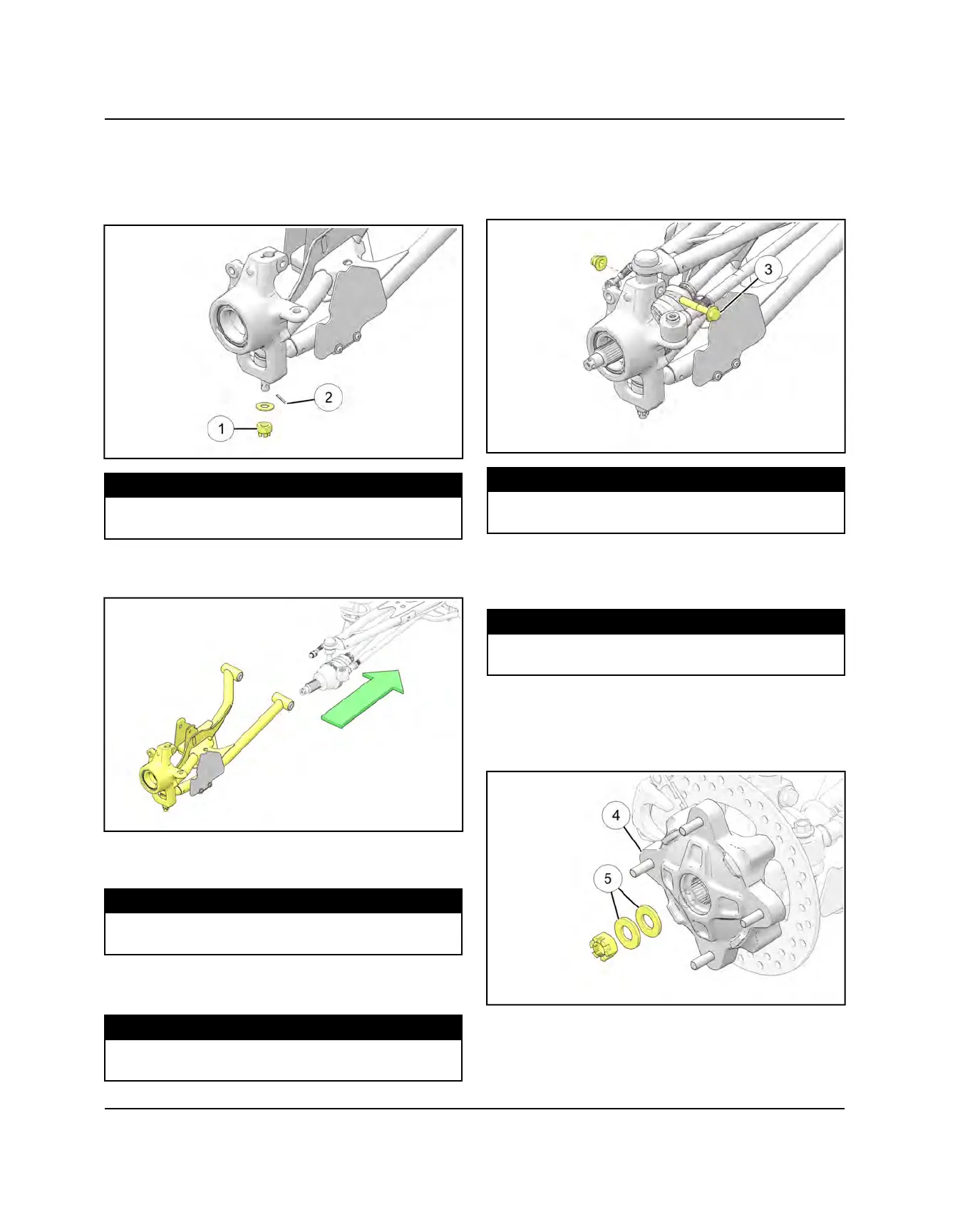
FRONT BEARING CARRIER INSTALLATION
1. Install the lower ball joint into the bearing carrier
using PA-51600. Install lower ball joint nut
q
and
torque to specification. Install anew cotter pin
w
.
TORQUE
Lower Ball Joint Nut:
45 ft-lbs (61 Nm)
2. Install drive shaft axle through the backside of the
bearing carrier.
3. Install lower A-arm assembly onto vehicle frame.
Torque new bolts to specification.
TORQUE
Lower Control Arm Fasteners:
42 ft-lbs (57 Nm)
4. Attach shock to A-arm with fastener. Torque lower
shock bolt to specification.
TORQUE
Shock Mounting Fastener:
42 ft-lbs (57 Nm)
5. Install the upper joint end into the front bearing
carrier.
6. Install a new upper ball joint pinch bolt
e
and nut.
Torque to specification.
TORQUE
Ball Joint Pinch Bolts:
42 ft-lbs (57 Nm)
7. Install the fastener retaining the front stabilizer bar
link to the upper control arm. Torque fastener to
specification.
TORQUE
Stabilizer Link Fasteners:
42 ft-lbs (57 Nm)
8. Apply Anti-Seize to drive shaft axle splines.
9. Install front wheel hub assembly
r
, cone washers
t
,
and hand tighten the castle nut. Install washers with
domed side out.
FINAL DRIVE

 Loading...