8.22
9929422 R02 - 2017-2019 ACE 900 Service Manual
© Copyright Polaris Industries Inc.
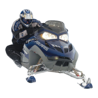
12.Remove the bearing carrier and lower A-arm from the
front drive shaft.
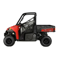
13.Remove the cotter pin
i
, lower ball joint nut
o
, and
washer
a
.
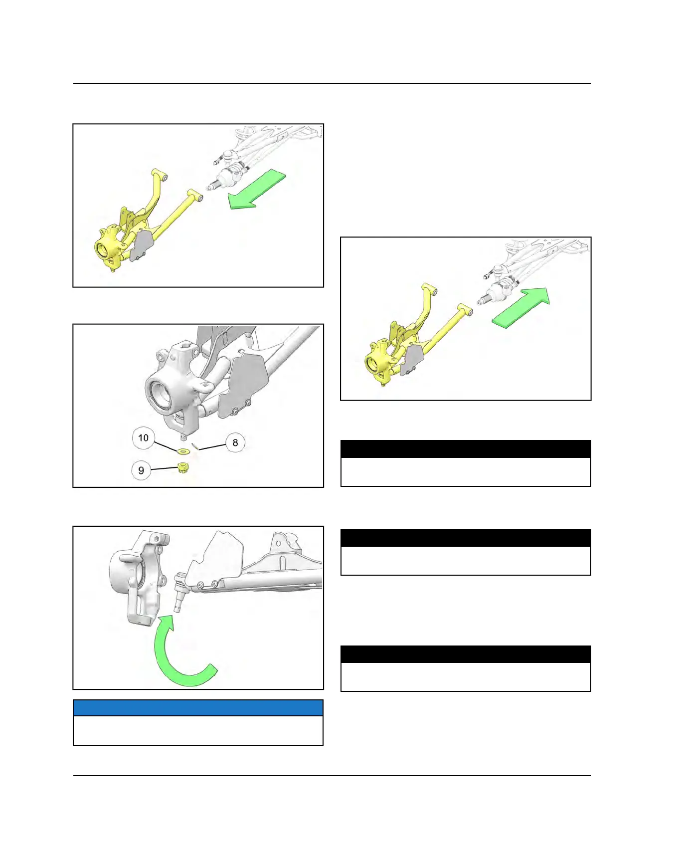
14.Separate the lower ball joint from the bearing carrier
using PA-51600.
NOTE
Proceed to Ball Joint Removal or if servicing the lower
Ball joint proceed to Lower Ball Joint Removal
15.Examine A-arm bushings and pivot tube. Replace if
worn. Discard hardware.
16.If not replacing the A-arm, thoroughly clean the A-arm
and pivot tube.
17.Install new ball joint into A-arm. Refer to “Ball Joint
Replacement” section.
18.Insert new A-arm bushings and pivot tube into new A-
arm. A light press force may be needed.
19.Install drive shaft axle through the backside of the
bearing carrier.
20.Install lower A-arm assembly onto vehicle frame.
Torque new bolts to specification.
TORQUE
Lower Control Arm Fasteners:
42 ft-lbs (57 Nm)
21.Attach shock to A-arm with fastener. Torque lower
shock bolt to specification.
TORQUE
Shock Mounting Fastener:
42 ft-lbs (57 Nm)
22.Install the upper joint end into the front bearing
carrier.
23.Install a new upper ball joint pinch bolt
e
and nut.
Torque to specification.
TORQUE
Ball Joint Pinch Bolts:
42 ft-lbs (57 Nm)
STEERING / SUSPENSION

 Loading...