3.62
9924880 Rev 2- 1/10/2014 - 2013 / 2014 RANGER XP 900 - 2014 RANGER XP 900 / CREW 900 Service Manual
© Copyright Polaris Sales Inc.
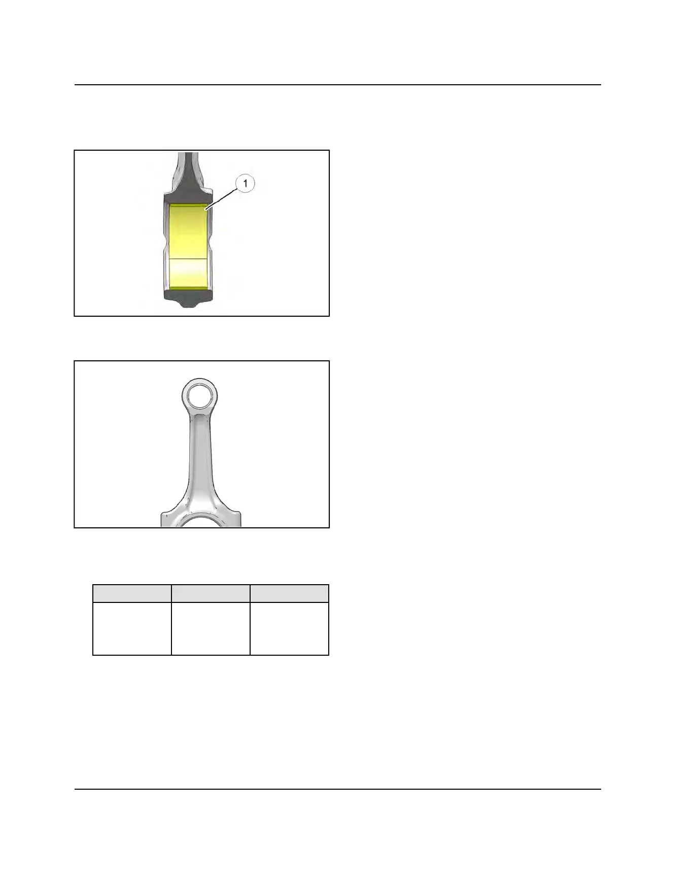
5. Using a dial bore gauge, measure big end I.D. in two
directions shown. Remove bearings when taking
measurements
q
. Record measurements and
compare to specifications.
6. Refer to the number printed onto the side of the
connecting rod, between the small and large bore
ends. This number represents the bore diameter.
7. The table below lists the big end bore diameter
specifications.
Connecting Rod Big End Bore Diameters
1 2 3
1.7318-
1.7321″
(43.989-
43.996 mm)
1.7321-
1.7323″
(43.996-
44.003 mm)
1.7323-
1.7326″
(44.003-
44.010 mm)
8. Whether using new connecting rods or re-installing
the original ones, refer to the bearing selection chart
provided in the “Connecting Rod Bearing Selection”
procedure in this chapter.
ENGINE
 Loading...