5
9924880 Rev 2- 1/10/2014 - 2013 / 2014 RANGER XP 900 - 2014 RANGER XP 900 / CREW 900 Service Manual
© Copyright Polaris Sales Inc.
5.37
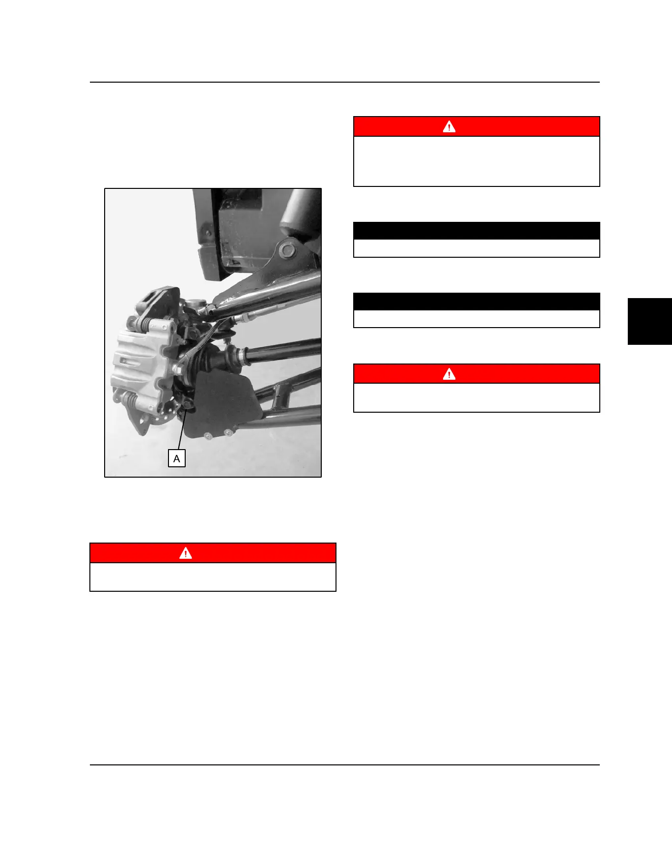
FRONT LOWER A-ARM REMOVAL
1. Properly lift and support the vehicle by the frame.
2. Remove the (4) wheel nuts and remove the wheel.
3. Using a 15mm socket and open-end wrench, remove
the lower ball joint pinch bolt (A) at the bearing
carrier.
4. Using a 15mm socket and open-end wrench, remove
the (2) fasteners retaining the lower A-arm to the
frame.
5. Remove the lower A-arm from the vehicle.
WARNING
Upon A-arm installation completion, test vehicle at low
speeds before putting into service.
FRONT LOWER A-ARM INSTALLATION
WARNING
The locking agent on the existing bolts was destroyed
during removal. DO NOT reuse old hardware. Serious
injury or death could result if fasteners come loose
during operation.
1. Install the lower A-arm onto the frame. Torque the
new lower A-arm fasteners to specification.
TORQUE
Lower A-Arm to Frame:40 ft-lbs (54 Nm)
2. Install the lower A-arm ball joint into the bearing
carrier. Torque the new fastener to specification.
TORQUE
Ball Joint Pinch Bolts:42 ft-lbs (57 Nm)
3. Install wheel and torque wheel nuts to specification
(see Chapter 2).
WARNING
Upon A-arm installation completion, test vehicle at low
speeds before putting into service.
BODY / STEERING / SUSPENSION
 Loading...