)LUVW6WHSV
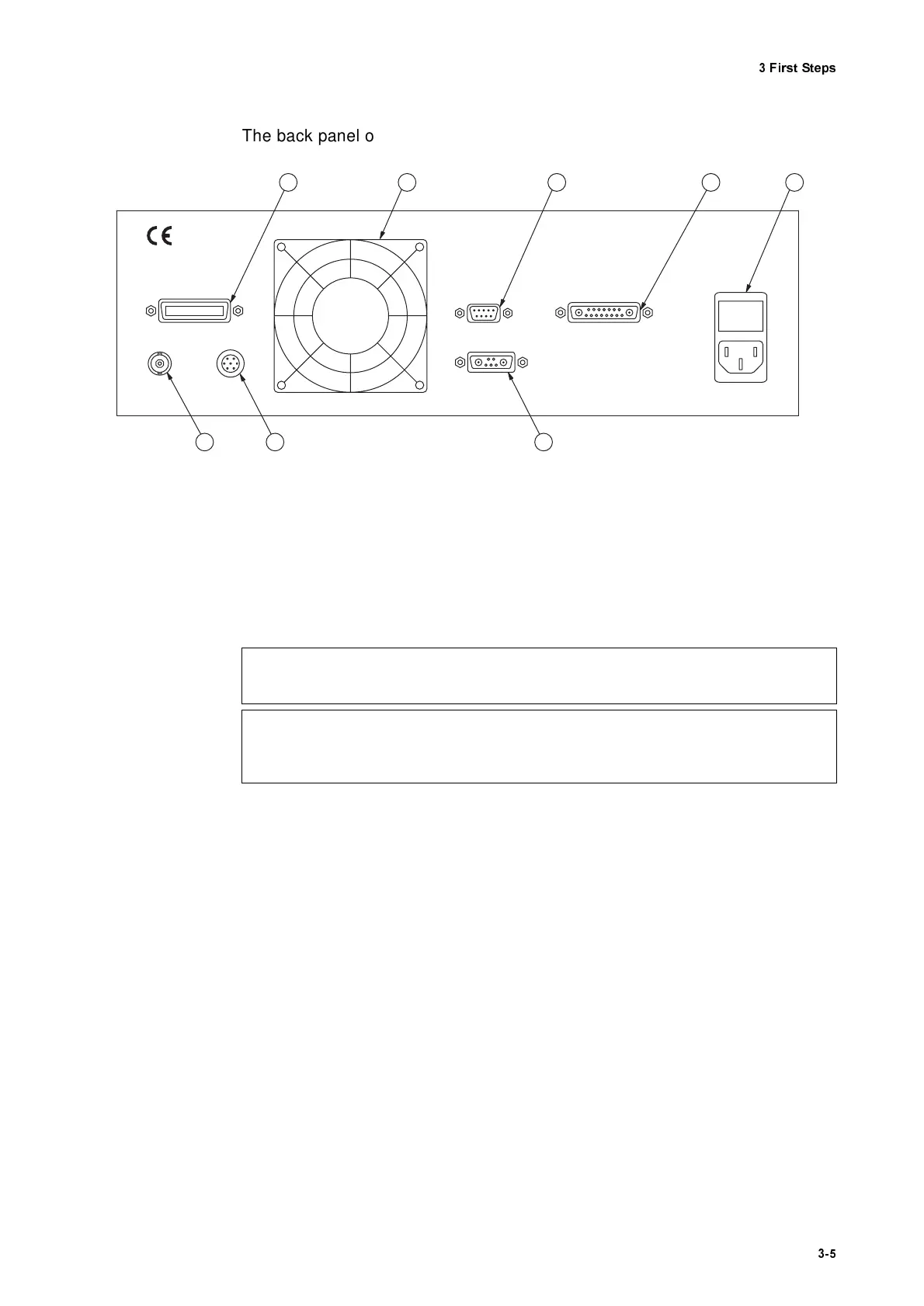
The back panel of the controller is shown in figure 3.2.
,17(5)(520(7 (5
- connector (Sub-D jack)
Jack for the connecting cable to the sensor head
0DLQVFRQQH FW LRQFRPEL QD WLRQ
Socket for standard power cord with built-in fuses and mains voltage
selector (refer to section 3.1)
(;7
ernal
'(&
oder - interface
Interface for the optional PC-based displacement decoder OFV-600 (refer
to section D.5.2)
5(027()2&86
- interface
Interface for the optional hand terminal OFV-310 to focus the laser beam
(refer to section A.1)
6,*1$/
- output (BNC jack)
The DC voltage at this output is proportional to the logarithm of the optical
signal level.
*3,% ,(((
- interface
Jack for the IEEE-488/GPIB cable (refer to appendix E)
Figure 3.2: Rear view of the controller
INTERFERO M ETER
R S 232
EXT. DEC.
SIG NAL
REM O TE FO C U S
G P IB / IE E E -4 8 8
6 7 8 1 2
5 4 3
:DUQLQJ
$OZD\V disconnect from the mains EHIRUH checking the fuses!
&DXWLR Q
$OZD\V check the setting of the voltage selector as well as the fuses EH IRU H installing the
controller!