12
#2 PCS: set ADD 2 down, ADD 1, 3, 4up.
NOTE: Either the USB flash drive or the SD card is provided to the device.
Removing it will cause the operation data lost.
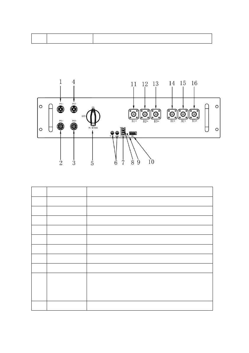
(4) Solar Controller
Figure 4.4.4: Solar Controller Front View
Table 4.4.4: Solar Controller Parts
Solar power input negative (-) #1.
Solar power input positive (+) #1.
Solar power input positive (+) #2.
Solar power input negative (-) #2.
Solar power input switch.
DC12V power supply output.
Communicate with other solar controller.
Communicate with EMS module.
Indicate the power status of PV module:
On: Power supply is normal.
Off: No power.
The communication address of solar controller.