FR | 11
EN
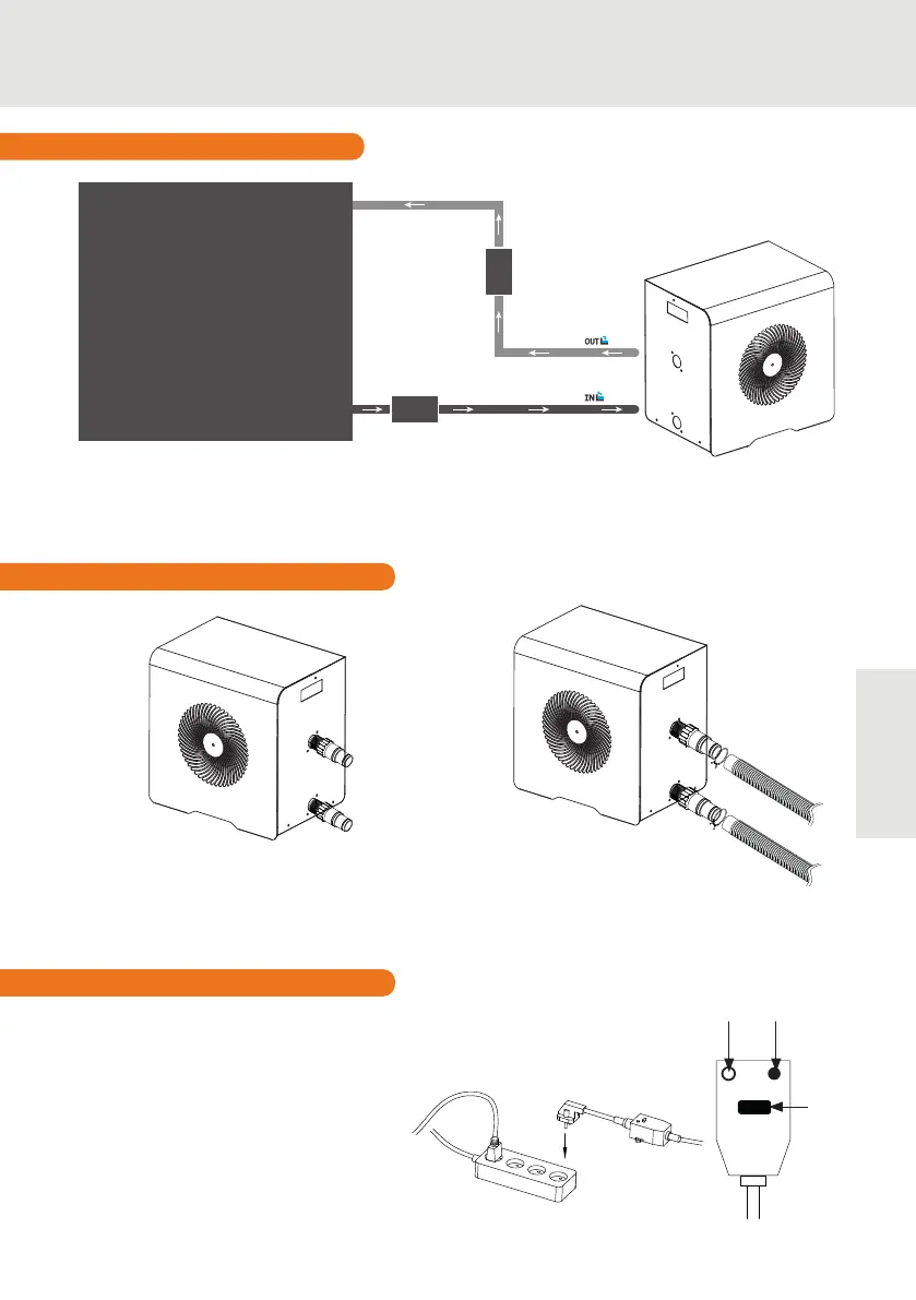
3.2 Installation layout
The lter located upstream of the heat pump must be regularly cleared so that the water in the
system is clean, thus avoiding the operational problems associated with dirt or clogging in the
lter.
TOWARDS THE POOL
Filtration + Pump
Automated treatment
system
FROM THE POOL
POOL
3. INSTALLATION
Step 1
Screw the connectors to the heat pump
Step 2
Connect the water outlet pipe and the water
intake pipe
3.3 Hydraulic connection
The heat pump electrical plug integrates
a 10mA dierential circuit breaker. Be-
fore connecting your heat pump, please
ensure that the plug is connected to the
ground.
The lter pump should function at the
same time as the heat pump. Therefore,
you need to connect them to the same
electrical circuit.
TOWARDS THE POOL
FROM THE POOL
3.4 Electrical connection
RESET
Test
Power
indicator
Reset