16
3. Installation
To function safely and maintain the integrity of your electrical system, the unit must be connected to a
general electricity supply in accordance with the following regulations:
Upstream, the general electricity supply must be protected by a 30 mA differential switch.
The heat pump must be connected to a suitable D-curve circuit breaker (see table below) in accordance
with current standards and regulations in the country where the system is installed.
The electricity supply cable must be adapted to match the unit’s rated power and the length of wiring
required by the installation (see table below). The cable must be suitable for outdoor use.
For a three-phase system, it is essential to connect the phases in the correct sequence.
If the phases are inverted, the heat pump’s compressor will not work.
In places open to the public, it is mandatory to install an emergency stop button close to the heat pump.
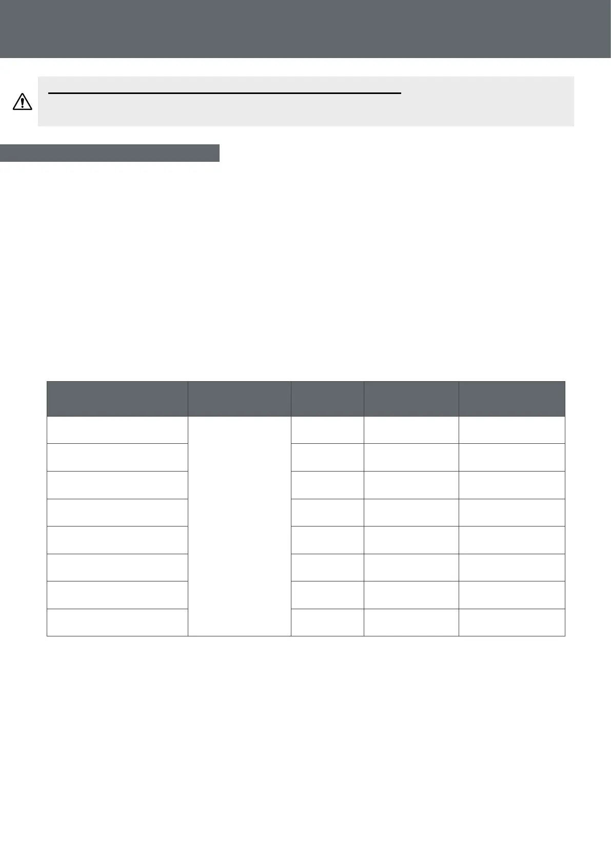
Models Electricity supply Max. current
Cable diameter
Protection
Thermal-magnetic (D
curve) protection
Silverline Mini
Single phase
230V~50Hz
4.9 RO2V 3x2.5 mm² 10A
Silverline 55
6.3 RO2V 3x2.5 mm² 10A
Silverline 70
8.9 RO2V 3x2.5 mm² 16A
Silverline 90
11.5 RO2V 3x2.5 mm² 16A
Silverline 120
13.5 RO2V 3x4 mm² 20A
Silverline 150
16.0 RO2V 3x4 mm² 20A
Silverline 180
18.5 RO2V 3x4 mm² 25A
Silverline 220
27.1 RO2V 3x6 mm² 32A
1
Cable cross-section suitable for max. length 30 metres. For longer than 30 metres, consult an electrician.
3.7 Electrical installation
WARNING: Installation must be carried out by a qualied engineer.
This section is provided for information purposes only and must be checked and adapted if
necessary according to the actual installation conditions.