PULSERPLUS PRO™ HIGH RESISTANCE GROUNDING SYSTEM
INSTALLATION, OPERATION AND MAINTENANCE INSTRUCTIONS
4750 Olympic Blvd. • Erlanger, KY 41018 • USA
Phone: 800-537-6144 / 859-283-0778 • Fax: 859-283-2978
www.postglover.com
Serving the Electrical Industry Since 1892
PGR Document #HG111-06© 2006 Post Glover Resistors, Inc.
PULSERPLUS PRO™ HIGH RESISTANCE GROUNDING SYSTEM
INSTALLATION, OPERATION AND MAINTENANCE INSTRUCTIONS
4750 Olympic Blvd. • Erlanger, KY 41018 • USA
Phone: 800-537-6144 / 859-283-0778 • Fax: 859-283-2978
www.postglover.com
Serving the Electrical Industry Since 1892
© 2006 Post Glover Resistors, Inc. 13
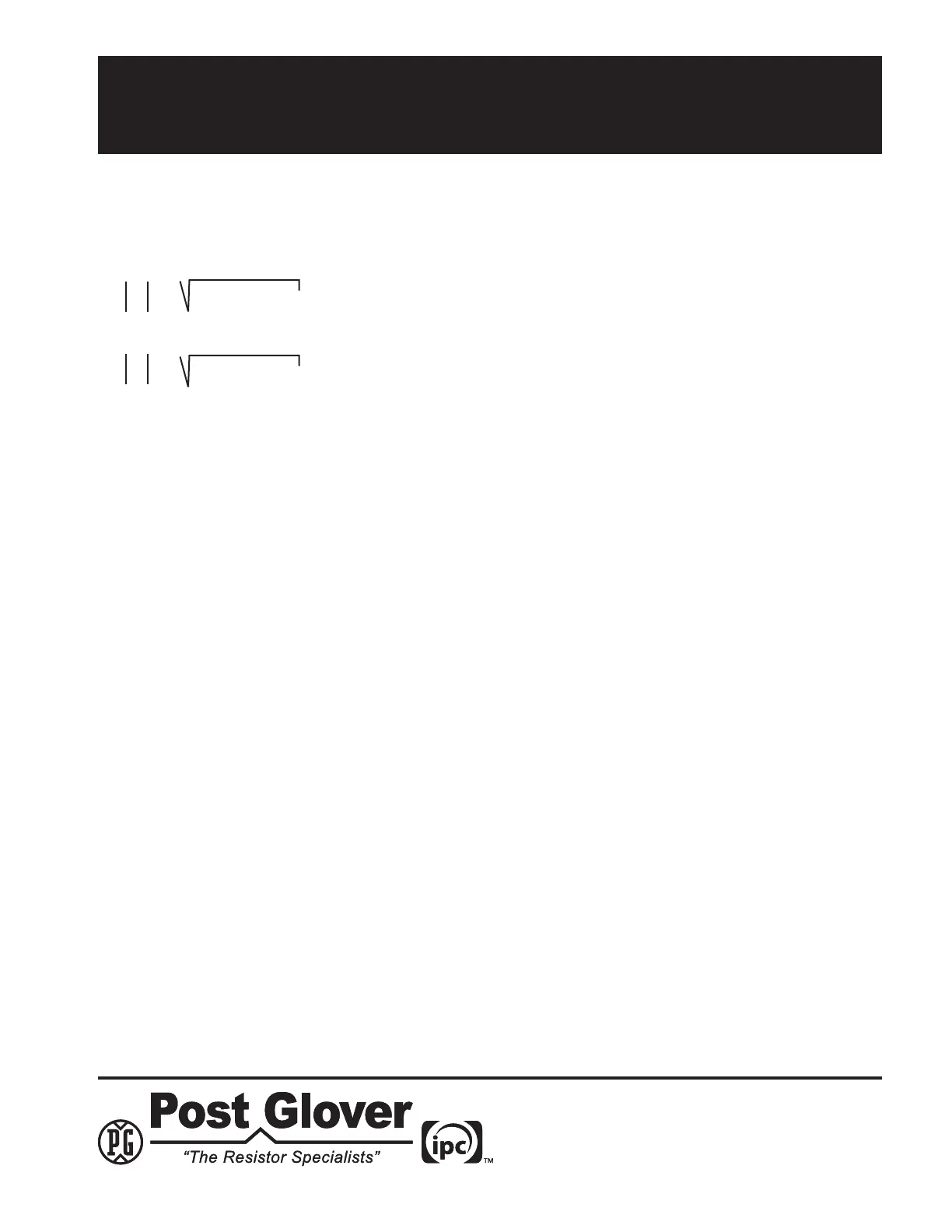
Charging Current Calculation
From Figure 1:
Ig=(IR)²+(IC) ²
Ic=(IG)²-(IR) ²
5.3 Test Results
All components that are operating during testing contribute to the test results. This includes the contribution of
thesurge-protectivecapacitorwhich,asmentionedpreviously,canbequitesignicant.Assuch,thetestresults
shouldbemodiedtoincludeallsurge-protectivecapacitorsnotinoperationduringtesting.
The resulting value should be used to determine a minimum current for ground fault alarming. Set the resistor
taps(seesection2)sothatthefaultcurrentisslightlygreaterthanIC.
NOTE: The temporary disconnect switch and current limiting fuse associated with the phase to be grounded are not
included with the PulserPlus Pro™. A portable ammeter can be included as an option with the PulserPlus Pro™.