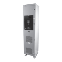
PULSERPLUS PRO™ HIGH RESISTANCE GROUNDING SYSTEM
INSTALLATION, OPERATION AND MAINTENANCE INSTRUCTIONS
4750 Olympic Blvd. • Erlanger, KY 41018 • USA
Phone: 800-537-6144 / 859-283-0778 • Fax: 859-283-2978
www.postglover.com
Serving the Electrical Industry Since 1892
PGR Document #HG111-06© 2006 Post Glover Resistors, Inc.
PULSERPLUS PRO™ HIGH RESISTANCE GROUNDING SYSTEM
INSTALLATION, OPERATION AND MAINTENANCE INSTRUCTIONS
© 2006 Post Glover Resistors, Inc. 6
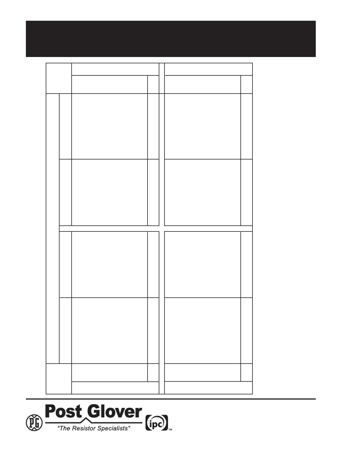
Field Condition
Over-Voltage
Over-Current
Under-Voltage
Under-Current
2.5 Summary of Events
Fundamental VoltageHarmonic Voltage
Fundamental CurrentHarmonic Current
On
Off
On
Off
On
Off
On
Off
1) Display changes to Fnd Vlt
Hi Limit
2) Fundamental timer begins
and expires
3) Normal light turns off
4) System Normal relay
changes state
5) Ground Fault light blinks
6) Grd Fault Alarm relay
changes state
7) Internal horn sounds
8) External Horn relay
changes state
No display or monitoring No display or monitoring No display or monitoring No display or monitoring
No display or monitoring No display or monitoring No display or monitoring No display or monitoring
IF ENABLED, SET TO 0 TO
DISABLE.
1) Display changes to Fnd Vlt
Lo Limit
2) Fundamental timer begins
and expires
3) Normal light turns off
4) System Normal relay
changes state
1) Display changes to Fnd
Amp Hi Limit
2) Fundamental timer begins
and expires
3) Normal light turns off
4) System Normal relay
changes state
5) Ground Fault light blinks
6) Gnd Fault Alarm relay
changes state
7) Internal horn sounds
8) External horn relay
changes state
IF ENABLED, SET TO 0 TO
DISABLE.
1) Display changes to Fnd
Amp Lo Limit
2) Fundamental timer begins
and expires
3) Normal light turns off
4) System normal relay
changes state
IF ENABLED, SET TO 0 TO
DISABLE.
1) Display changes to Hrm Vlt
Lo Limit
2) Harmonic timer begins
and expires
3) Normal light turns off
4) System normal relay
changes state
IF ENABLED, SET TO 0 TO
DISABLE.
1) Display changes to Hrm
Amp Lo Limit
2) Harmonic timer begins
and expires
3) Normal light turns off
4) System Normal relay
changes state
1) Display changes to Hrm
Vlt Hi Limit
2) Harmonic timer begins
and expires
3) Normal light turns off
4) System Normal relay
changes state
5) Third Harmonic light blinks
6) Third Harmonic relay
changes state
7) Internal horn sounds
8) External Horn relay
changes state
1) Display changes to Hrm
Amp Hi Limit
2) Harmonic timer begins
and expires
3) Normal light turns off
4) System Normal relay
changes state
5) Third Harmonic light blinks
6) Third Harmonic relay
changes state
7) Internal horn sounds
8) External Horn relay
changes state
Presing Alarm Silence Button:
1) Turns off Internal horn
2) Resets External horn relay
Pressing Pulse Button:
1) Amber light blinks
2) Pulsing relay begins
Pressing Reset Button:
1) Resets Display
2) Resets all latching relays
3) Only does above if Auto
Reset is turned off
Pressing Reset and Down Arrow Buttons:
1) Enters Setup mode