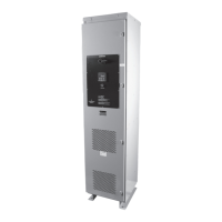
PULSERPLUS PRO™ HIGH RESISTANCE GROUNDING SYSTEM
INSTALLATION, OPERATION AND MAINTENANCE INSTRUCTIONS
4750 Olympic Blvd. • Erlanger, KY 41018 • USA
Phone: 800-537-6144 / 859-283-0778 • Fax: 859-283-2978
www.postglover.com
Serving the Electrical Industry Since 1892
PGR Document #HG111-06© 2006 Post Glover Resistors, Inc.
PULSERPLUS PRO™ HIGH RESISTANCE GROUNDING SYSTEM
INSTALLATION, OPERATION AND MAINTENANCE INSTRUCTIONS
4750 Olympic Blvd. • Erlanger, KY 41018 • USA
Phone: 800-537-6144 / 859-283-0778 • Fax: 859-283-2978
www.postglover.com
Serving the Electrical Industry Since 1892
© 2006 Post Glover Resistors, Inc. 11
Section 5 – Testing System Capacitive-charging Current
5.1 General
The magnitude of zero-sequence charging current is determined by the line-to-ground capacitance associated
with system components. The value of the current must be known to properly coordinate the Post Glover High-
Resistance Grounding System. In an industrial power system where the design and components are known,
the charging current can be estimated with reasonable accuracy. With a complex array of machines and cables
this may be tedious and yield less-than-accurate results. The discussion that follows outlines a suitable test for
determining the value of current in a system. A transformer’s capacitance-to-ground is usually negligible because
of the large spacing between the transformer’s core and winding, and the shielding effect of the winding layer
adjacenttothecore.Shieldingpreventstheotherwindinglayersfromsignicantlyincreasingthewinding-to-
groundcapacitance.Cableandoverheadlinecapacitance,ontheotherhand,canbesignicantifthecircuitis
large.
Major contributions to the overall system capacitance-to-ground are made by rotating machines. Attributes such
as the type of insulation and the number and depth of slots can produce wide variations. A typical value for a 200-
hp, 2300-volt, 1800-rpm induction motor might be 0.002 micro-farads phase-to-ground capacitance.
The most accurate way to determine the maximum value of the charging current is by test, since extreme
variations can exist. The charging current per phase is represented by ICA, ICB or ICC while IC corresponds to
the total line-to-ground charging current. To obtain the zero-sequence charging current, one phase conductor is
intentionally grounded as shown in Figure 1 below.
5.2 Test Procedure
Thetestprocedureisasfollows(refertoFigure1onpage12):
1. Temporarily install a disconnect switch, a current limiting fuse and a portable ammeter in the path
between the phase to be tested and earth ground, as shown in Figure 1 below.
DO NOT CLOSE
TEMPORARY DISCONNECT UNTIL SW1 IS CLOSED.
2. ClosethedisconnectswitchinthePulserPlusPro™cabinet(SW1)toprovideareturnpathtomeasure
current returning through the neutral grounding resistor.
3. Closethetemporarydisconnectswitchinstalledonthephasetobegrounded(asshowninFigure1)in
the system.
4. Withbothdisconnectswitchesclosed,currentthroughthegroundedphase(IG) can be read by the
portableammeterandcurrentthroughtheneutralgroundingresistor(IR) can be read by the PulserPlus
Pro™ Display unit.
5. After the test is completed and all data is collected, open the temporary disconnect switch associated with
thegroundedphasebeforeopeningthedisconnectswitch(SW1)inthePulserPlusPro™cabinet.
6. Usethechargingcurrentcalculationsbelowtondthetotalline-to-groundchargingcurrent(IC).