PULSERPLUS PRO™ HIGH RESISTANCE GROUNDING SYSTEM
INSTALLATION, OPERATION AND MAINTENANCE INSTRUCTIONS
4750 Olympic Blvd. • Erlanger, KY 41018 • USA
Phone: 800-537-6144 / 859-283-0778 • Fax: 859-283-2978
www.postglover.com
Serving the Electrical Industry Since 1892
PGR Document #HG111-06© 2006 Post Glover Resistors, Inc.
PULSERPLUS PRO™ HIGH RESISTANCE GROUNDING SYSTEM
INSTALLATION, OPERATION AND MAINTENANCE INSTRUCTIONS
© 2006 Post Glover Resistors, Inc. 14
Section 6 – Controller Setup
6.1 Power Up Display
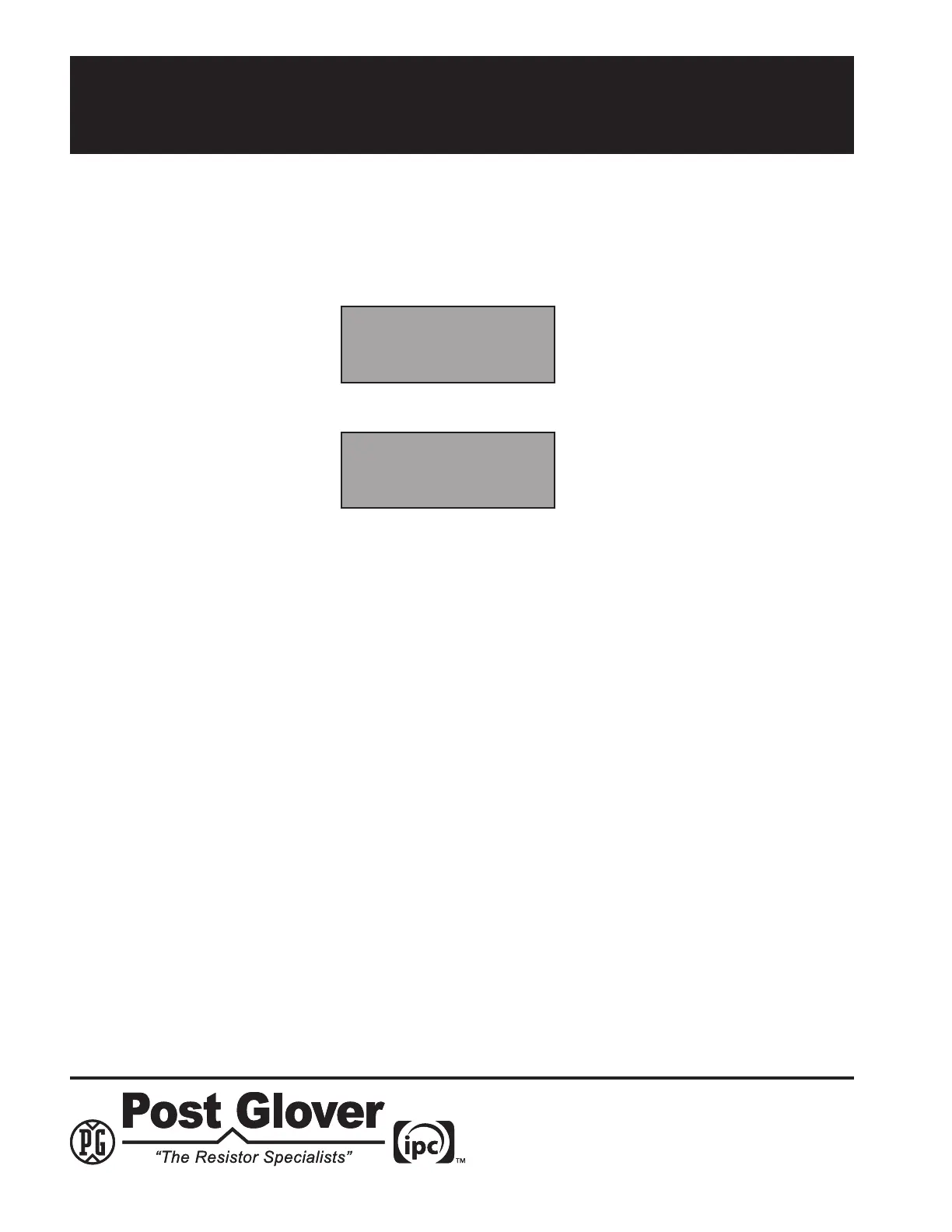
1. Apply AC power to the unit. After a 1/2 second beep, the following message will be displayed for 5 seconds:
2. The unit then goes through a short self check. During the self check, the following message will be displayed:
3. Once the self check is complete, the display unit will display the fundamental and/or 3
rd
harmonic voltage
and/or the amperage of the grounded system by automatically toggling between the screens. The unit may be
programmed to display any or all of these measurements.
6.2 Adjustable Parameters
The following features of the PulserPlus Pro™ can be set from the front panel.
Fundamental Voltage Measurement On/Off
Harmonic Voltage Measurement On/Off
Fundamental Amperage Measurement On/Off
Harmonic Amperage Measurement On/Off
CT Ratio On/Off
Fundamental Voltage Hi Limit nnn V
Fundamental Voltage Lo Limit nnn V
Harmonic Voltage Hi Limit nnn V
Harmonic Voltage Lo Limit nnn V
Fundamental Amp Hi Limit nn.n A
Fundamental Amp Lo Limit nn.n A
Harmonic Amp Hi Limit nn.n A
Harmonic Amp Lo Limit nn.n A
Pulse Time Sec n.n S
Fundamental Alarm Delay nn.n S
Harmonic Alarm Delay nn.n S
Auto Reset On/Off
Post Glover
PulserPlus Pro
Self-Test
SW Version (x.x)