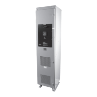
PULSERPLUS PRO™ HIGH RESISTANCE GROUNDING SYSTEM
INSTALLATION, OPERATION AND MAINTENANCE INSTRUCTIONS
4750 Olympic Blvd. • Erlanger, KY 41018 • USA
Phone: 800-537-6144 / 859-283-0778 • Fax: 859-283-2978
www.postglover.com
Serving the Electrical Industry Since 1892
PGR Document #HG111-06© 2006 Post Glover Resistors, Inc.
PULSERPLUS PRO™ HIGH RESISTANCE GROUNDING SYSTEM
INSTALLATION, OPERATION AND MAINTENANCE INSTRUCTIONS
© 2006 Post Glover Resistors, Inc. 16
Set CT Ratio OFF ON ON ON
Selection: 1X 0.57x 2x 6x
Press the UP ARROW or DOWN ARROW buttons to select the desired ratio, then press ENTER to store the parameter.
This feature multiplies the measured current by the selected CT ratio. For example, the physical limitation of
the PulserPlus Pro™ module is 16A. If 20A is desired, a 30:5 CT is used to send a 0-5A signal the module. The
CTratioissetfor6x,sothemeasuredcurrent(0to5A)ismultipliedby6x.Thedisplayandalarmingusesthis
multipliedcurrent(0to30A).
Default setting for the CT ratio is Off, 1X. The CT ratio is factory set to the proper rating for the installed
components.
6.6 Hi Limit Setpoints
The Hi Limits are only accessible if the associated measurement display is enabled.
The Hi Limit setpoint indicates the level at which the Ground Fault or Third Harmonic alarm will activate.
Using the UP ARROW and DOWN ARROW buttons, the voltage hi limits may be set to any voltage between 0
and 400 volts. For Medium Voltage applications, see the schematic prints provided with the unit for information on
setting this value. The amperage hi limits may be adjusted between 00.0 and 16.0 amps.
6.7 Lo Limit Setpoints
The Lo Limits are only accessible if the associated measurement display is enabled.
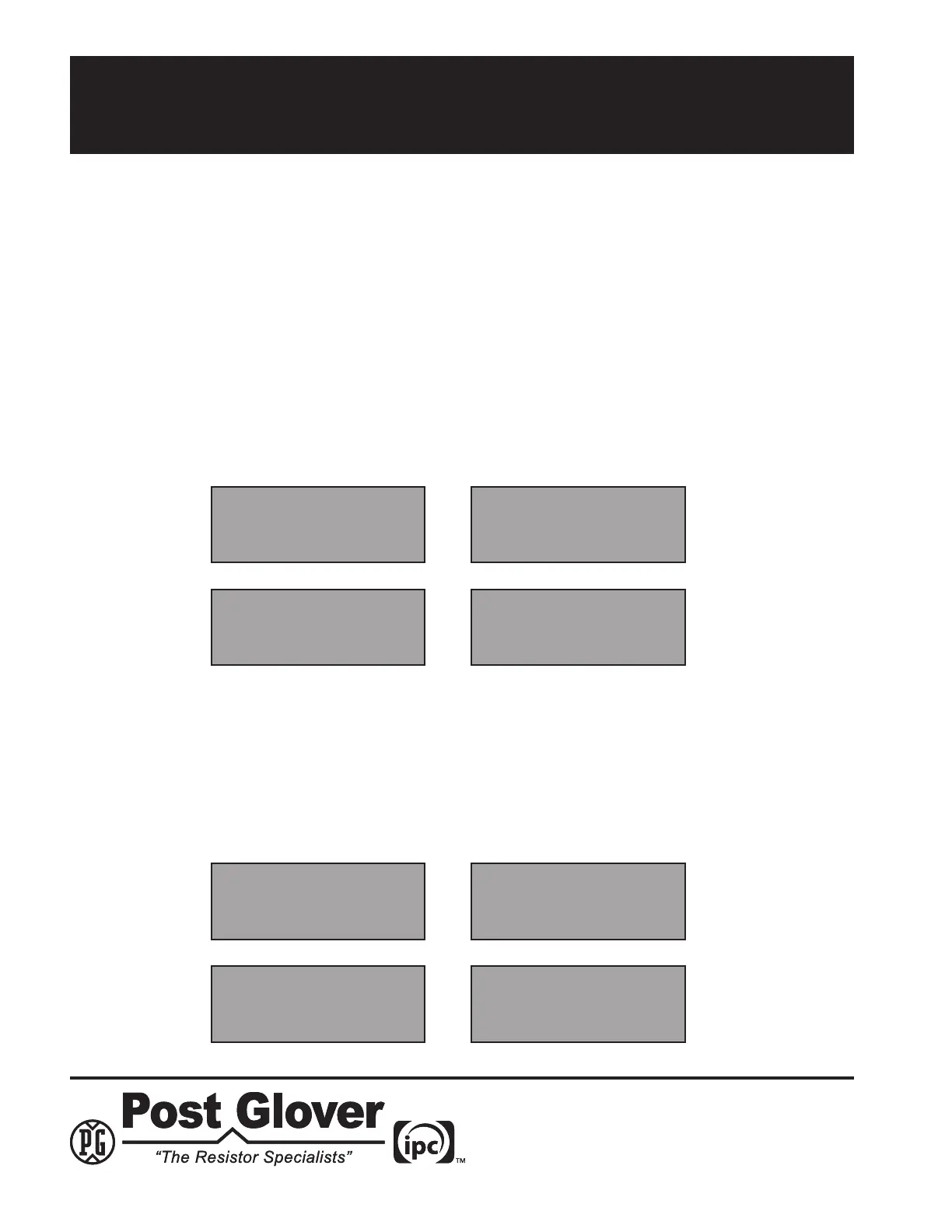
Setpoint 010 V
Fnd Vlt Hi Limit
Setpoint 065 V
Hrm Vlt Hi Limit
Setpoint 06.0 A
Fnd Amp Hi Limit
Setpoint 12.0 A
Hrm Amp Hi Limit
Setpoint 000 V
Fnd Vlt Lo Limit
Setpoint 000 V
Hrm Vlt Lo Limit
Setpoint 00.0 A
Fnd Amp Lo Limit
Setpoint 00.0 A
Hrm Amp Lo Limit