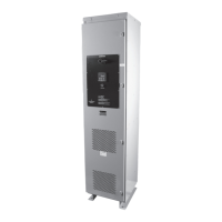
PULSERPLUS PRO™ HIGH RESISTANCE GROUNDING SYSTEM
INSTALLATION, OPERATION AND MAINTENANCE INSTRUCTIONS
4750 Olympic Blvd. • Erlanger, KY 41018 • USA
Phone: 800-537-6144 / 859-283-0778 • Fax: 859-283-2978
www.postglover.com
Serving the Electrical Industry Since 1892
PGR Document #HG111-06© 2006 Post Glover Resistors, Inc.
PULSERPLUS PRO™ HIGH RESISTANCE GROUNDING SYSTEM
INSTALLATION, OPERATION AND MAINTENANCE INSTRUCTIONS
© 2006 Post Glover Resistors, Inc. 4
Section 2 – Operational Description
2.1 Normal Operation
Please refer to the drawings supplied with your unit for ratings and other information. Section 9 contains
schematics and dimension drawings with information for standard systems. For low-voltage systems, Figures 3
and 4 show wye-connected and delta-connected schematics respectively. For medium-voltage systems, wye-
connected and delta-connected schematics can be found in Figures 5 and 6 respectively.
Duringnormaloperation,onlyaninsignicantcapacitive-chargingcurrent,unbalancedharmoniccurrent,and/or
leakagecurrentowsthroughtheresistor(Adescriptionofcapacitive-chargingcurrentisprovidedinSection
5). The display will show this current and/or voltage. The green NORMAL indicating light on the operator’s panel
will be illuminated.
The PulserPlus Pro™ controller detects Fundamental Current and/or Voltage and 3
rd
Harmonic Current and/or
Voltage for both over- and under-conditions. Each of the four can be independently disabled by turning the feature
OFF, and the under-conditions can be disabled by entering a 0 value. A common time delay setting is used for all
Fundamental alarming and a separate common time delay setting is used for all 3
rd
Harmonic alarming.
2.2 Loss of Ground
Whenthecurrentmentionedabovegoestozero,typicallythisindicatesaLossofGroundcondition(i.e.
grounding wire failure). If this occurs, the system will be Ungrounded. The PulserPlus Pro™ controller has an
Under-Current / Under-Voltage feature that detects this condition for both Fundamental and 3
rd
Harmonics.
Upon detection, the green NORMAL indicating light will turn off and its auxiliary form-C contacts change state.
This feature can be disabled by setting its value to zero.
2.3 Ground Fault
When a ground fault occurs, the resistor acts to limit the ground current to a pre-determined low value. Fault
current magnitude can be set by adjusting the taps provided on the resistor. Fault current shall be set so that
thefaultcurrentisslightlygreaterthanthesystem’snaturalcapacitive-chargingcurrent(seeSection5).
The fundamental voltage appearing across the resistor or the fundamental amperage through the resistor is
sensed by the PulserPlus Pro™ controller. To prevent nuisance indications, a variable time delay is entered via
the operator’s panel. When the time delay expires, the red GROUND FAULT indicator light will start to blink,
the NORMAL indicator light will turn off, and an alarm horn will sound. Upon detection, SYSTEM NORMAL and
GROUND FAULT auxiliary form-C contacts change state.
The alarm horn can be silenced by pressing the ALARM SILENCE button while searching for the cause of the
ground fault. The red GROUND FAULT indicator light will continue blinking until the ground fault is removed and
the system is manually reset by pressing the RESET and ALARM SILENCE buttons. Optionally, the PulserPlus
Pro™canbeconguredforauto-reset.