PFC-4064 KEYPAD PROGRAMMING • 8870080 • REV A • 12/17
Section 2: Pre-Programming Procedures and Defaults
Before beginning PFC-4064 programming, install the panel following the directions included in the PFC-4064 Installation
and Operations Manual (Potter document # 5403638). Failure to properly install and wire the physical panel and any devices/
accessories being used in conjunction with it can result in system errors and difculty in programming, as well as potentially
damaging the re alarm system.
System Defaults: Input Circuit
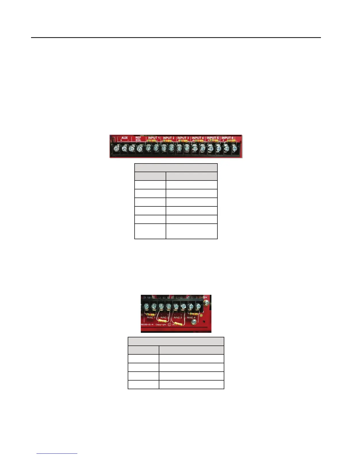
The PFC-4064 has a total of 6 built-in input circuits available for use. These inputs are for monitoring devices such as smoke
detectors, pull stations and waterow switches. The terminals for input devices (shown below) are located at the top right
corner of the control panel’s circuit board. Each circuit has a factory default setting that can be used to connect to a specic
type of input device for ease of installation and programming.
System Defaults: Output Circuit
The PFC-4064 has a total of 4 built-in output notication appliance circuits (NACs) available for use. These outputs are for
notication devices, The output NAC terminals (shown below) are located at the bottom right corner of the control panel’s
circuit board. Each circuit has a factory default setting that can be used to connect to a specic type of output device for ease
of installation and programming.
Input Terminal Default Settings
Terminal # Setting Type
1 Waterow
2 Smoke
3 Pull Station
4 General Fire Alarm
5 General Fire Alarm
6 Non-latching
Tamper Supervisory
NAC Output Terminal Default Settings
Terminal # Activation Setting Type
1 Waterow Only
2 Any Alarm
3 Any Alarm
4 Any Alarm
2