6
4. SYSTEM DESCRIPTION
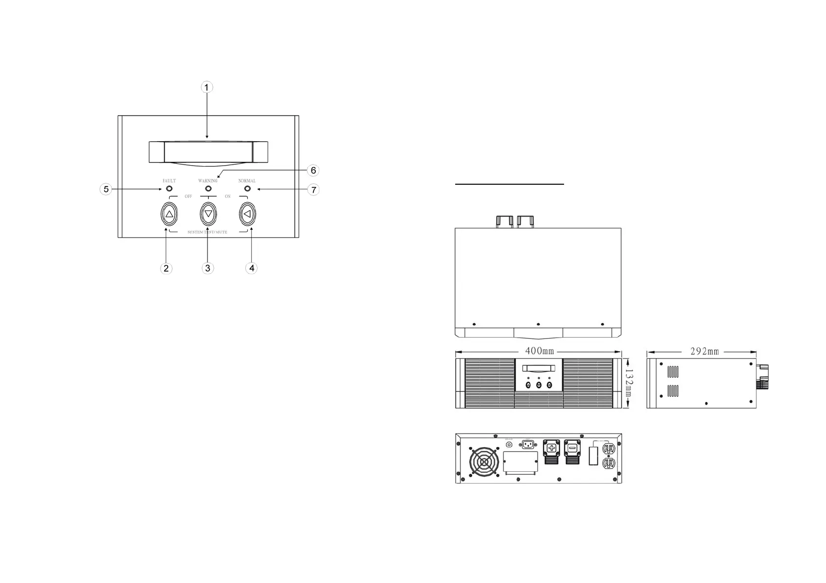
4.1 Front Panel Description for LCD Model
1. LCD Display: This indicates the Solar Inverter operation information,
including Solar Inverter status, input/output voltage, input/output frequency,
battery voltage, battery capacity left, output load, inside temperature, and
the times of history events.
2. Up-key: Use to select upward the Solar Inverter status on LCD Display.
3. Down-key: Use to select downward the Solar Inverter status on LCD
Display. Beside, press it simultaneously with the Up-key to switch off the
Solar Inverter.
4. Enter-Key: It is pressed with the Down-key to turn on the Solar Inverter. In
battery operation mode, press it with Up-key at the same time to disable
the buzzer. Beside, it is pressed to confirm and enter the item selected.
5. Fault LED (red): To indicate the Solar Inverter is in fault condition because
of inverter shutdown or over-temperature.
7
6. Warning LED (yellow): To indicate the Solar Inverter is in the status of
overload, bypass and battery back-up.
7. Normal LED (green): To indicate the Solar Inverter is operating normally.
8. ON/TEST/MUTE key: It should be pressed with the control key
simultaneously to switch on Solar Inverter, do Solar Inverter auto-test in
normal AC mode and turn off the buzzer in battery operation.
4.2 Outline Description
800W Rack Mount Type