19
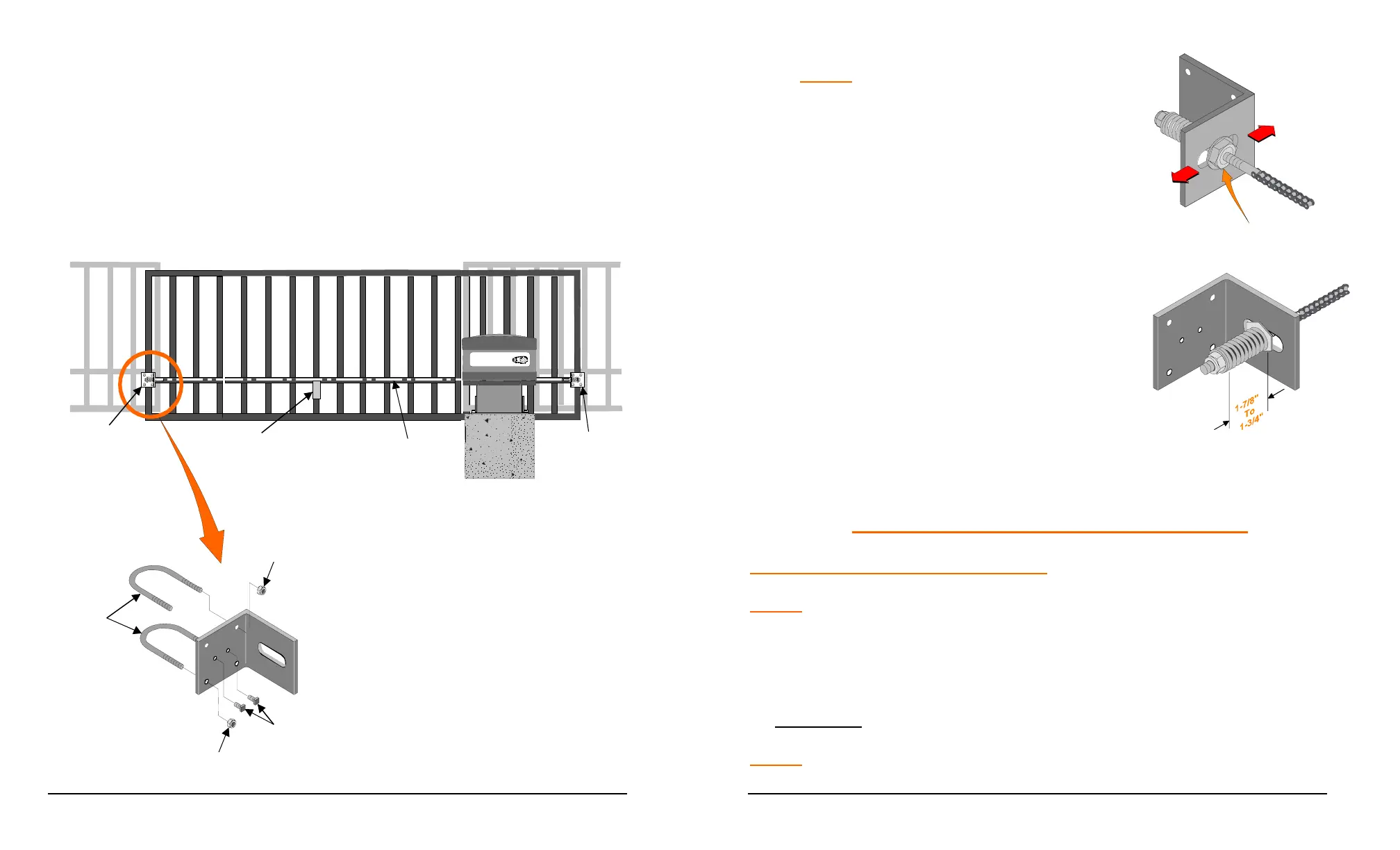
7. Pull the chain through to the opposite end of the gate. Cut the chain to the
correct length, attach remaining chain take-up bolt and install in the gate
bracket as in steps 2 through 4.
8. Adjust the gate bracket height at both ends of the gate to insure the drive
chain aligns with the operator idler sprockets.
9. Tighten the gate brackets securely and lock in position with the setscrews
provided.
Power Mast er
Gate
Bracket
Chain
Support
Bracket
Drive Chain
Gate
Bracket
U-Bolts
Nut
Nut
Set
Screw
20
NOTE: By moving the gate manually to
each end of its travel, chain alignment
is simplified.
11. Adjust chain tension so that the chain
tension springs are reduced to a length
within 1-7/8” and 1-3/4”.
ELECTRICAL SET-UP AND CONNECTIONS
CONNECTION OF INCOMING POWER
NOTE: Wiring to operator must use watertight materials in accordance with local
electric code. See wire gauge/distance charts for proper sizing. Master/Slave
installations should have SEPARATE power supply wiring or length of wire runs
should be figured at half that shown on the chart. This unit must be grounded
in accordance with N.E.C. and local codes.
WARNING: DO NOT APPLY POWER UNTIL TOLD TO DO SO! RISK OF
SHOCK OR INJURY MAY RESULT.
NOTE:
Before connecting the operator to an incoming power supply, use a
voltmeter to determine that the electrical service is the same as that on the
Adjust Spring Length
As Shown For Proper
Chain Tension
Jamb Nut
 Loading...