33
9. Check position of dipswitch #2 to be sure it coincides with the installation.
(Left Hand or Right Hand) If this is correct and operator is 1Ø consult the
factory. (1-800-243-4476).
10. If dipswitch #2 is in the correct position and the operator is 3Ø, switch two
incoming leads and repeat step #5.
▲ WARNING: UNDER NO CIRCUMSTANCES SHOULD THE CONTROL
STATION WIRING BE ALTERED IF THE ROTATION IS INCORRECT. TO
DO SO WILL CAUSE SOME CONTROL FUNCTIONS TO BE
INOPERATIVE, AND MAY RESULT IN PERSONAL INJURY OR DAMAGE
TO THE GATE AND/OR OPERATOR.
11. If the operator functions properly, run the operator to the open limit switch and
turn off the power.
12. If there is still a distance before the gate is fully open, turn off power, move
the open limit nut away from the open limit switch a few turns and turn on the
power.
13. Press the OPEN button again to check how much further the gate opened.
14. Continue this procedure until the OPEN limit is set.
NOTE: When making fine adjustments, turn the limit nut ¼ to ½ turn at a time;
reconnect power and test run the gate.
15. Repeat procedure for the CLOSE limit adjustment.
NOTE: Open and Close Limit Switches are Reversed for slide left to Open
Operation.
16. After the desired open and close position of the gate has been obtained,
make certain that a groove in both limit nuts are engaged by the pressure
plate.
OPEN LIMIT SWITCH
For Slide Right To Open
Operation
Pressure Plate
Limit nut
Limit nut
CLOSE LIMIT SWITCH
for slide right to open
operation
Limit Shaft
34
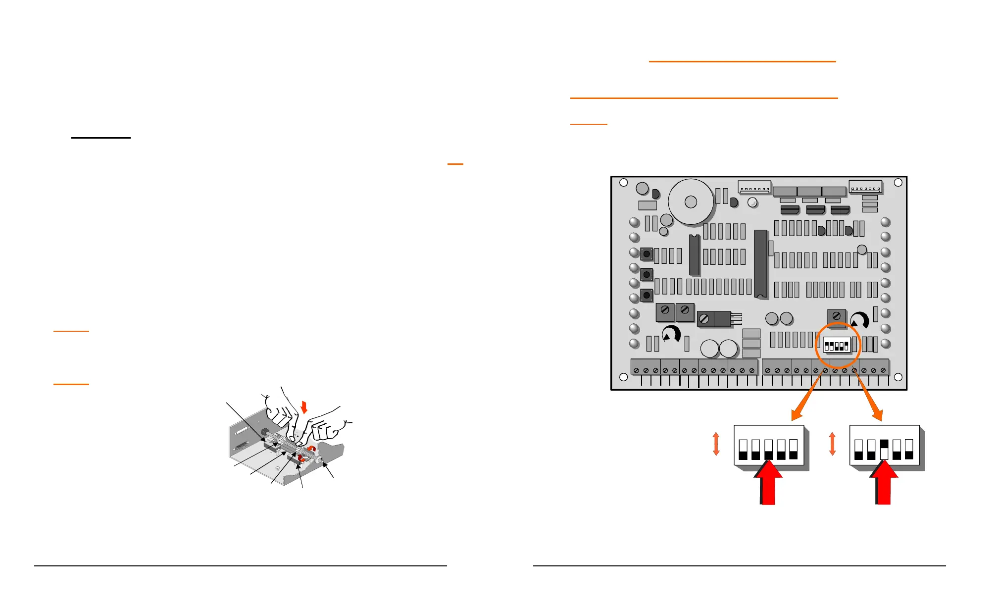
CONTROL CONNECTIONS
CONNECTION OF A THREE-BUTTON STATION:
NOTE: All control contacts must be NORMALLY OPEN unless
dipswitch #3 is placed to the “ON” position, which will change the
circuitry to accept a NORMALLY CLOSED STOP BUTTON.
COM
COM
COM
24V
AC
24V
AC
ALT
RDO
OPN
CRO
FRE
OPN
CLO
STO
COM
COM
COM
OPN
PHO
CLO
PHO
SHW
REV
OPN
EDG
CLO
EDG
MST
OPN
MST
CLO
COM
COM
COM
OPEN
PUSH
FREE
EXT
ALT
RADIO
OPN/
CLO
RADIO
OPEN
CLOSE
PUSH
STOP
PUSH
CLOSE
PHOTO
OPEN
PHOTO
LD18
LD10
LD11
LD12
LD15
LD14
LD16
LD17
LD13
OPEN
CLOSE
STOP
OPEN CLOSE
FORCE
ADJUSTMENT
AUTO
RECLOSE
TIMER
OFF MAX
MID
LIMIT
REV
LOOP
OPN
EDGE
CLO
EDGE
RH OPN
LH CLO
LIMIT
RH CLO
LH OPN
LIMIT
MOTOR
OPEN
MOTOR
CLOSE
SHAD OW
LOOP
LD19
LD2
LD3
LD4
LD5
LD6
LD8
LD9
LD7
12
3
4
5
POWER
LD1
P3
P4
TB1
TB2
U1
U2
U4
12
3
4
5
ON
OFF
12
3
4
5
for Normally
Open Stop
Button
ON
OFF
for Normally
Closed Stop
Button
 Loading...