17
ATTACHING DRIVE CHAIN
1. Install gate brackets at each end of the gate with U-bolts provided. Do not
fully tighten at this time.
2. Attach a chain take up bolt to one end of the drive chain using a #50
connecting link.
3. Install spring fittings into gate brackets using ¾” nuts and lock washers.
DO NOT tighten.
4. Install chain take up bolt, previously attached to the chain, into spring
fitting in furthest gate bracket. Secure it in position with spring, spring
washer, and ½” elastic stop nut.
Powe r Mas te r
Cement
Pad
Gate
Leading Edge
Gate
Extension
Gate
Bracket
Chain
Support
Bracket
Drive Chain
Gate
Bracket
Chain Support
Bracket
Chain Support
Back up plate
Bolt
Washer
Nut
Gate
Bracket
1/2-13 Elastic
Stop Nut
Spring
Washer
Chain
Tensioning
Spring
Spring
Fitting
3/4 Internal Tooth
Lock Washer
3/4-10 Jamb Nut
Chain take-up Bolt
#50 Connecting Link
Install Chain Support
Brackets As Required
Nut
3/8"
U-Bolts
18
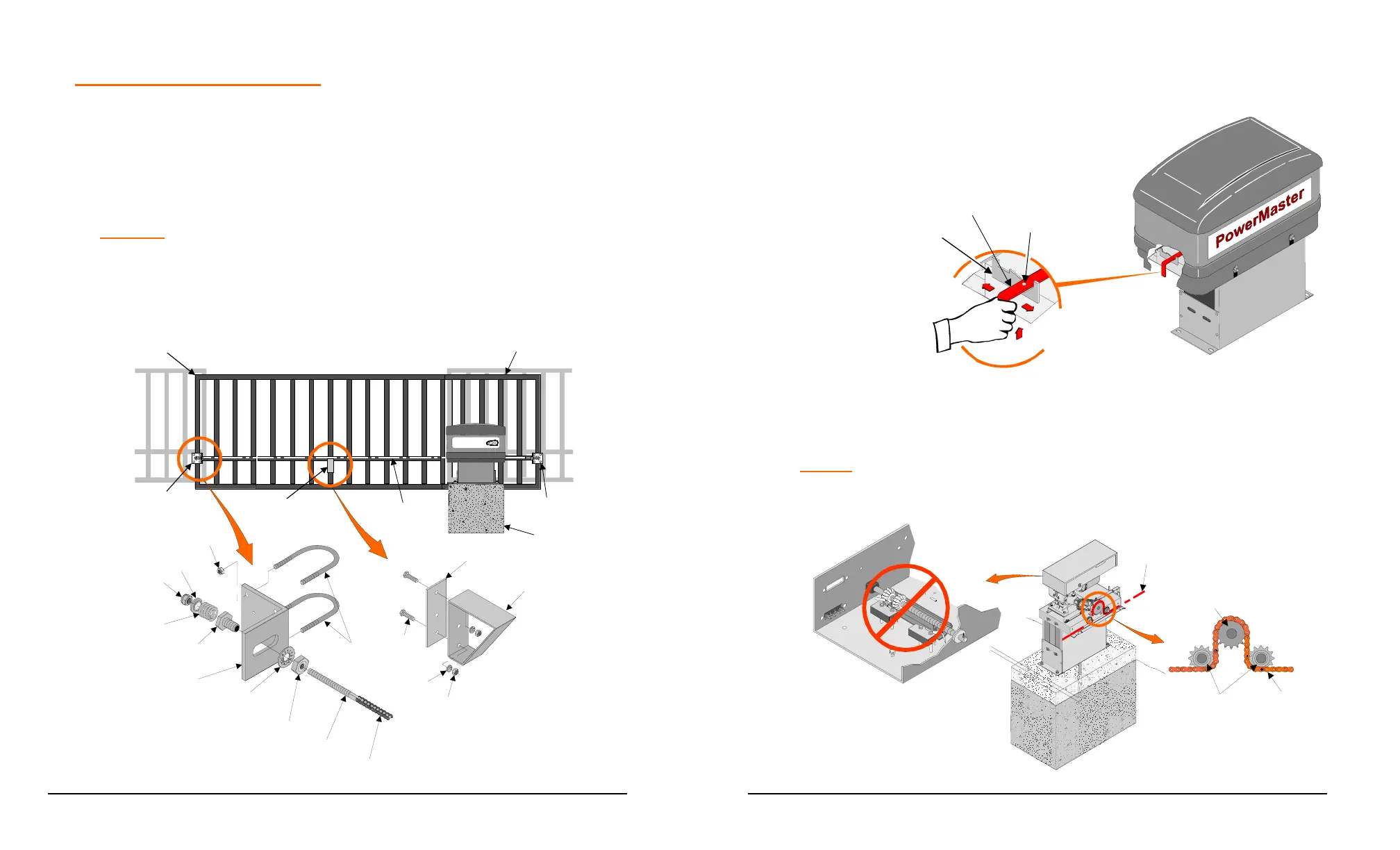
5. Disengage operator by moving the red disconnect lever (Located on
the operator base at the opposite end from the motor) to the
disconnect position, and latch in place.
6. Thread free end of chain under first idler sprocket, up and over drive
sprocket, then under the second idler sprocket.
NOTE: When pulling chain through operator sprockets, the limit nuts in the
electric box can be driven passed their normal position. Reset the limit
nuts as necessary.
Drive
Sprocket
Idler
sprockets
Drive
Chain
Drive
Chain
To Re-Engage Drive:
Lift Lever To Unlatch,
Then Move Lever To
The Right.
To Disconnect Drive:
Move Lever To The Left Until
It Latches In Retaining
Bracket.
Padlock
Option Hole
Retaining
Bracket
Disconnect
Lever
 Loading...