27
AUDIBLE PRE - MOVE WARNING
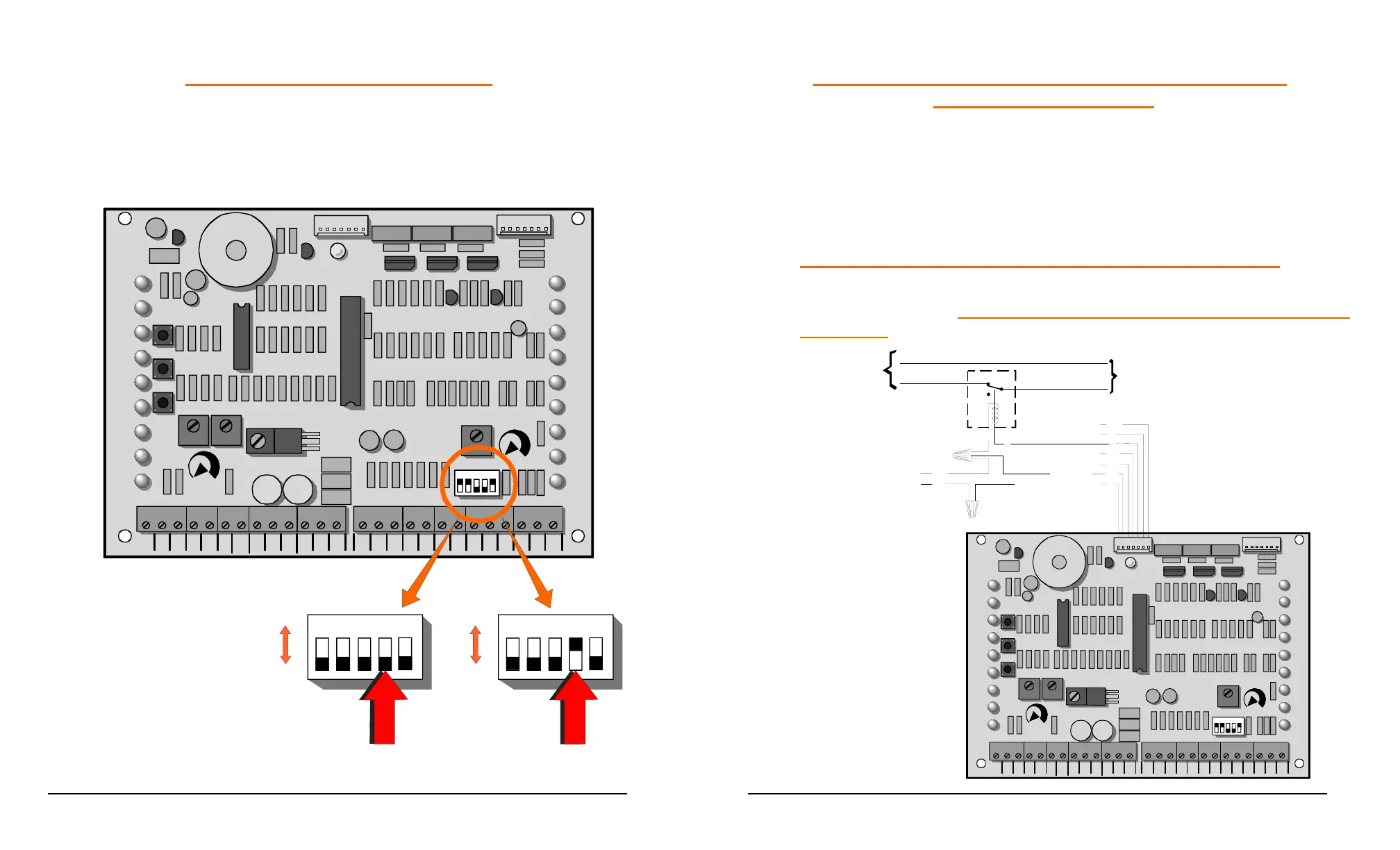
By moving Dipswitch #4 to the “ON” position the option of a 3 second Audible
Warning, before gate movement, may be selected.
COM
COM
COM
24V
AC
24V
AC
ALT
RDO
OPN
CRO
FRE
OPN
CLO
STO
COM
COM
COM
OPN
PHO
CLO
PHO
SHW
REV
OPN
EDG
CLO
EDG
MST
OPN
MST
CLO
COM
COM
COM
OPEN
PUSH
FREE
EXT
ALT
RADIO
OPN/
CLO
RADIO
OPEN
CLOSE
PUSH
STOP
PUSH
CLOSE
PHOTO
OPEN
PHOTO
LD18
LD10
LD11
LD12
LD15
LD14
LD16
LD17
LD13
OPEN
CLOSE
STOP
OPEN CLOSE
FORCE
ADJUSTMENT
AUTO
RECLOSE
TIMER
OFF MAX
MID
LIMIT
REV
LOOP
OPN
EDGE
CLO
EDGE
RH OPN
LH CLO
LIMIT
RH CLO
LH OPN
LIMIT
MOTOR
OPEN
MOTOR
CLOSE
SHADOW
LOOP
LD19
LD2
LD3
LD4
LD5
LD6
LD8
LD9
LD7
12345
POWER
LD1
P3
P4
TB1 TB2
U1
U2
U4
12
3
4
5
ON
OFF
12
3
4
5
OFF ON
ON
OFF
Audible
Pre-move Warning
Option
28
AUXILIARY CIRCUIT FOR USE WITH GATE LOCKS,
WARNING LIGHTS, ETC
An auxiliary 24 VAC power circuit, for use with a 24V control relay, has
been provided. This circuit will be activated just prior to gate movement
and will continue to be active until the gate stops. It may be used to
control a gate lock, activate warning lights and solenoid controlled devices
or any other system required during this time interval. Two control options
are available.
OPTION #1 – POWER REMOVED DURING GATE MOVEMENT
Below is a diagram showing the connection of a device, such as a
magnetic gate lock, requiring the removal of power during the gate
movement.
COM
COM
COM
24V
AC
24V
AC
ALT
RDO
OPN
CRO
FRE
OPN
CLO
STO
COM
COM
COM
OPN
PHO
CLO
PHO
SHW
REV
OPN
EDG
CLO
EDG
MST
OPN
MST
CLO
COM
COM
COM
OPEN
PUSH
FREE
EXT
ALT
RADIO
OPN/
CLO
RADIO
OPEN
CLOSE
PUSH
STOP
PUSH
CLOSE
PHOTO
OPEN
PHOTO
LD18
LD10
LD11
LD12
LD15
LD14
LD16
LD17
LD13
OPEN
CLOSE
STOP
OPEN CLOSE
FORCE
ADJUSTMENT
AUTO
RECLOSE
TIMER
OFF MAX
MID
LIMIT
REV
LOOP
OPN
EDGE
CLO
EDGE
RH OPN
LH CLO
LIMIT
RH CL O
LH OPN
LIMIT
MOTOR
OPEN
MOTOR
CLOSE
SHADOW
LOOP
LD19
LD2
LD3
LD4
LD5
LD6
LD8
LD9
LD7
12
3
4
5
POWER
LD1
P3
P4
TB1
TB2
U1
U2
U4
To Gate Locks,
Warning Lights, Ect.
R
WH
R
Y
GY
BK
WH
GND (Common)
24 VAC
From
Transformer
Power In
To Aux. Device
Relay With
24 VAC Coil
WH
Y
BR
WH
N.O.
N.C.
Power leg
Neutral
Aux. Circuit Using
Normally Closed
Control Relay
 Loading...