15
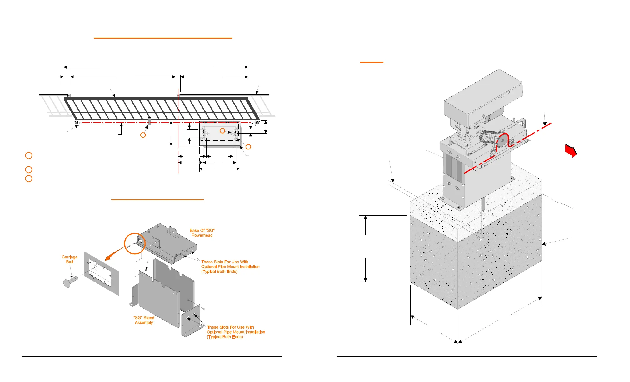
INSTALLATION OF CEMENT PAD
Lay out the cement pad as shown. Be sure top surface is level. Allow 2 days
cure time before installing operator. Bolt pattern must be parallel to the gate.
INSTALLATION TO PAD
1. Assemble stand and mount power head using carriage bolts.
Nut
7-1/2"
16-5/8"
22"
30"
14"
11-3/4"
9"
Fence
10-1/2"
3-3/4"
A
Gate
Opening
Gate
B
40" Min.
Min. Gate Length = Gate Opening +A +B +40"
C
L
Of Drive Chain
Gate
Bracket
3
1
2
1 3" O.D. Pipe, Extending Min. 18" Above Ground
Only Required For Optional Post Mounting (2) Places.
2 1/2" Mounting Hardware (4) Places ( Not Supplied).
14" X 30"
Cement
Pad
3 Install Chain Support Bracket As Required.
16
2. Using ½” hardware (Not Supplied) bolt assembled unit to the pad,
being sure to align operator parallel to the fence.
NOTE: Sprockets must face the fence.
In Ground
Depth As Required
By Local Code
Conduit Depth
As Required
By Local Code
Cement Pad
Drive
Chain
14"
30"
FENCE
 Loading...