37
2. Choose ONE of the options below for the connection of a FOUR-WIRE radio
control receiver to the control board terminal strip.
NOTE: If your radio’s connecting wires are not color coded as shown, see
the radio’s installation manual to determine which wires are for the
normally open contacts and which require the 24 VAC Power Supply.
N.O.
CONTACT
Four Wire
Radio Reciever
Wired For
"OPEN/CLOSE"
Four Wire Radio Reciever
Wired For "OPEN" Only
NOTE: Must Be Used With
Timer to Close Option.
GY
BK
GY
R
GY
BK
GY
R
COM
COM
COM
24V
AC
24V
AC
ALT
RDO
OPN
CRO
FRE
OPN
CLO
STO
COM
STOP
PUSH
CLOSE
PHOTO
OPEN
PHOTO
LD16
LD17
LD13
FORCE
ADJUSTMENT
TB1
U4
COM
COM
COM
24V
AC
24V
AC
ALT
RDO
OPN
CRO
FRE
OPN
CLO
STO
COM
STOP
PUSH
CLOSE
PHOTO
OP EN
PHOTO
LD16
LD17
LD13
FORCE
ADJUSTMENT
TB1
U4
24 VAC
N.O.
CONTACT
24 VAC
CONNECTIONS FOR
OPEN/CLOSE OPERATION
CONNECTIONS FOR
OPEN ONLY OPERATION
1. For electrical connections of a four-wire radio receiver via the external
terminal strip. See below.
NOTE: Internal wiring for the radio control terminal strip is factory set-up for the
OPEN ONLY option. For the OPEN/CLOSE option, move the wire on the control
board terminal strip from the “RDO OPN” terminal to the ‘CRO” terminal.
RADIO
R1
R2
R3
GY
R
BK
GY
R4
N.O.
CONTACT
RADIO CONTROL
TERMINAL
24 VAC
38
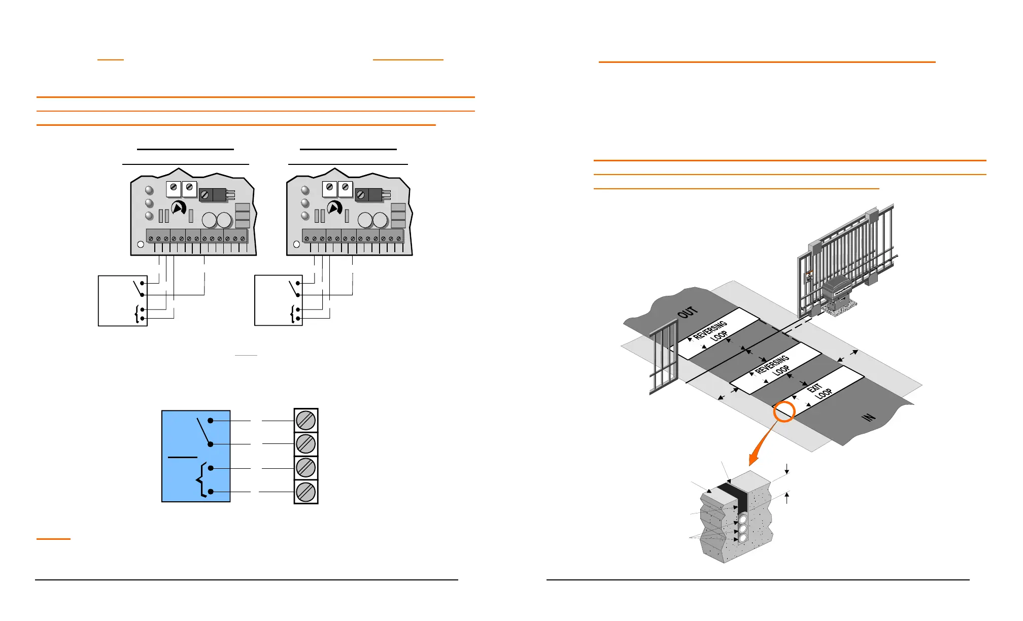
LOOP DETECTOR SYSTEMS AND INSTALLATION
The diagram below depicts the typical loop options for a Slide Gate installation.
1. The Exit Loop provides a signal to open the gate when a vehicle enters
the loop zone.
2. The Reversing Loops protect a vehicle in the loop zone from being
contacted with the gate by overriding any close signal while the
gate is open, and by reversing the gate if closing.
4'
4'
4'
4'
4'
4'
4'
4'
Road Surface
Sealant
Loop wires
Min 1"
3/16" To 1/4"
Saw Slot
 Loading...