41
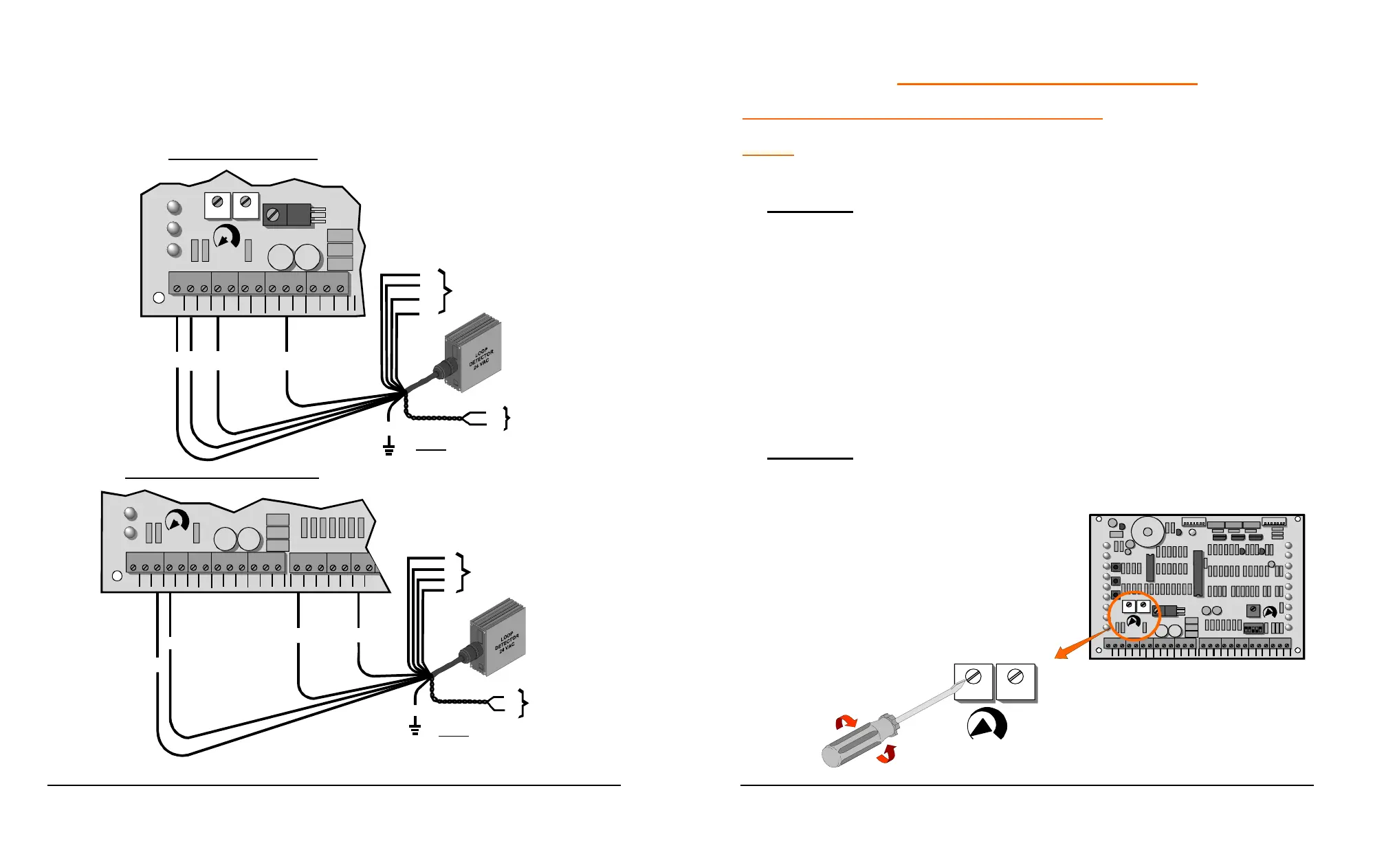
7. Mount the loop detector in the operator and connect the wire loop.
8. Connect loop detector to the control board as shown in the following
diagrams.
V
OR
R
P
Not Used
BL
BK
WH
Y
GR
BR
GY
TO
DRIVEWAY
LOOP
REVERSING LOOP CONNECTION
NOTE: TWIST LEADS APPOX.
6 TURNS PER FOOT.
COM
COM
COM
24V
AC
24V
AC
ALT
RDO
OPN
CRO
FRE
OPN
CLO
STO
COM
COM
COM
OPN
PHO
CLO
PHO
SHW
REV
OPN
EDG
CLOSE
PHOTO
OPEN
PHOTO
LD17
LD13
FORCE
ADJUSTMENT
TB1
TB2
V
OR
R
P
Not Used
BL
BK
WH
Y
GR
BR
GY
TO DRIVEWAY
LOOP
NOTE: TWIST LEADS APPOX.
6 TURNS PER FOOT.
COM
COM
COM
24V
AC
24V
AC
ALT
RDO
OPN
CRO
FRE
OPN
CLO
STO
COM
STOP
PUSH
CLOSE
PHOTO
OPEN
PHOTO
LD16
LD17
LD13
FORCE
ADJUSTMENT
TB1
U4
EXIT LOOP CONNECTION
42
SAFETY DEVICE CONNECTIONS
INHERENT OBSTRUCTION SENSING DEVICE:
NOTE: The gate MUST move smoothly and easily in manual operation before
attempting this adjustment.
▲ WARNING: TURN OFF POWER TO OPERATOR WHEN MAKING ANY
ADJUSTMENTS.
This unit is supplied with a speed sensing system, which will stop the gate when
it encounters an obstruction and then backs the gate off approximately 2 inches.
If the gate is started again and a second encounter occurs before hitting a limit
switch, the gate will stop and sound a warning signal. A constant pressure
control will then be needed to start the gate. This sensing system has sensitivity
adjustments located on the printed circuit board. The force required to activate
the system may be adjusted in both OPEN and CLOSE directions separately.
Start at minimum and increase force setting until it is just over what is required to
move the gate smoothly without any nuisance tripping.
▲ WARNING: NEVER INCREASE FORCE SETTING TO MAKE UP FOR A
GATE THAT IS NOT MAINTAINED PROPERLY. THIS WILL DESENSITIZE
THE OPERATION OF THE SAFETY SYSTEM.
COM
COM
COM
24V
AC
24V
AC
ALT
RDO
OPN
CRO
FRE
OPN
CLO
STO
COM
COM
COM
OPN
PHO
CLO
PHO
SHW
REV
OPN
EDG
CLO
EDG
MST
OPN
MST
CLO
COM
COM
COM
OPEN
PUSH
FREE
EXT
ALT
RADIO
OPN /
CLO
RADIO
OPEN
CLOSE
PUSH
STOP
PUSH
CLOSE
PHOTO
OPEN
PHOTO
LD18
LD1 0
LD11
LD12
LD15
LD14
LD16
LD17
LD13
OPEN
CLOSE
STOP
OPEN C LOSE
FORCE
ADJUSTMENT
AUTO
RECLOSE
TIMER
OFF M AX
MID
LIMIT
REV
LOO P
OPN
EDGE
CLO
EDGE
RH OPN
LH C LO
LIM IT
RH CLO
LH OP N
LIM IT
MOTOR
OPEN
MOTOR
CLOSE
SHADOW
LOO P
LD19
LD2
LD3
LD4
LD5
LD6
LD8
LD9
LD7
12345
POWER
LD1
P3
P4
TB1 TB2
U1
U2
U4
OPEN CLOSE
FORCE
ADJUSTMENT
MIN. MAX.
Location Of
Drive Force
Adjustment
MIN.
MAX.
 Loading...