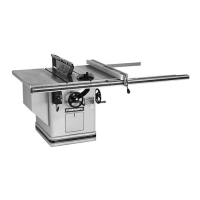
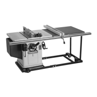
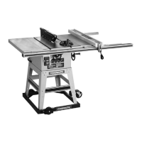
Model 72 -
12"/14"
Tilting Arbor Saw
OPERATING INSTRUCTIONS
MACHINE INSTALLATION ADJUSTMENTS AND MAINTENANCE
RECEIVING:
Remove saw from shipping container and check for damage.
Report
any damage
to
your
distributor
immediately. Accessories and rails were shipped in separate cartons. Clean protective coating from
the table, extensions and fence. Read the instruction manual thoroughly for assembly, alignment,
maintenance
and
safety instructions.
INSTALLATION:
Mount
machine on a solid foundation and lag
to
the floor through the four lag screw holes provided
in the machine base. Mount table extensions, leveling them
to
the table using a straight edge so
that
they form a flat plane with the table top. Install the
front
(graduated) and rear rails with the hard-
ware provided. Slide the fence and carriage assembly
on
the mounting rails. Mount the splitter and
guard assembly. Install the miter gauge in its left-hand slot.
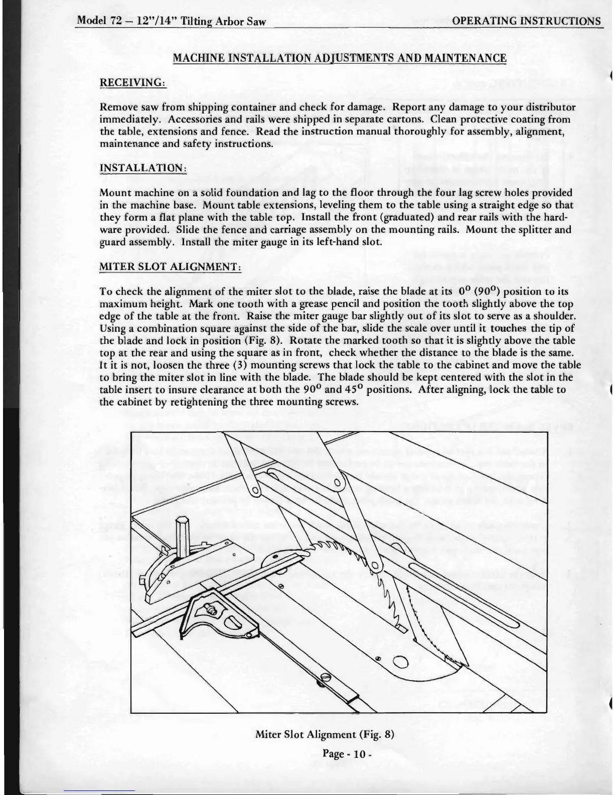
MITER SLOT ALIGNMENT:
To check the alignment
of
the miter slot
to
the blade, raise the blade
at
its 0
0
(90
0
)
position
to
its
maximum height. Mark one
tooth
with a grease pencil and position the
tooth
slightly above the top
edge
of
the
table
at
the
front. Raise the miter gauge bar slightly
out
of
its slot
to
serve
as
a shoulder.
Using a combination square against the side
of
the bar, slide the scale over until
it
touches the tip
of
the blade and lock in position (Fig. 8).
Rotate
the marked
tooth
so
that
it
is slightly above the table
top
at
the rear and using
the
square
as
in front, check whether
the
distance
to
the blade
is
the same.
It
it
is
not, loosen the three (3) mounting screws
that
lock the table
to
the cabinet and move the table
to
bring the miter slot in line with the blade. The blade should be
kept
centered with the slot in the
table insert
to
insure clearance
at
both
the 90
0
and 45
0
positions.
After
aligning, lock the table to
the cabinet by retightening the three mounting screws.
Miter Slot Alignment (Fig. 8)
Page -
10-
 Loading...