Model 71 -
12';/14"
Tiltine: Arbor Saw
OPERATING INSTRUCTIONS
MACHINE INSTALLATION ADJUSTMENTS AND MAINTENANCE
cont'd
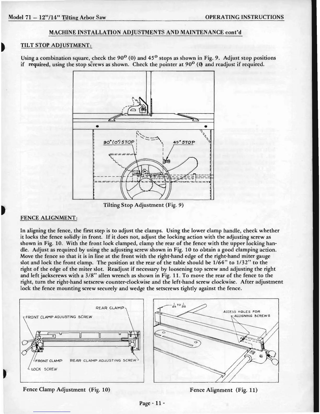
TILT STOP ADJUSTMENT:
Using a combination square, check the 90
0
(0) and 45
0
stops
as
shown in Fig. 9. Adjust
stop
positions
if
required, using
the
stop screws
as
shown. Check the pointer
at
90
0
«b
and readjust
if
required .
•
•
Tilting
Stop
Adjustment (Fig. 9)
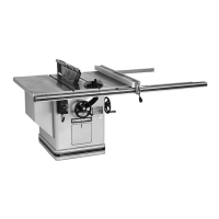
FENCE ALIGNMENT:
In aligning the fence, the first step
is
to
adjust the clamps. Using the lower clamp handle, check whether
it
locks the fence solidly in front.
If
it
does not, adjust the locking action with the adjusting screw
as
shown in Fig. 10. With the
front
lock clamped, clamp the rear
of
the fence with
the
upper
locking han-
dle. Adjust
as
required by using the adjusting screw shown in Fig. 10 to obtain a good clamping action.
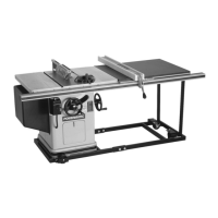
Move the fence so
that
it
is
in line
at
the
front
with the right-hand edge
of
the
right-hand miter gauge
slot and lock the
front
clamp. The position
at
the rear
of
the table should be
1/64"
to
1/32"
to the
right
of
the edge
of
the miter slot. Readjust
if
necessary by loosening
top
screw and adjusting the right
and left jackscrews with a
3/8"
allen wrench
as
shown in Fig. 11.
To
move the rear
of
the
fence to
the
right,
tum
the right-hand setscrew counter-clockwise and the left-hand screw clockwise.
After
adjustment
lock the fence mounting screw securely and wedge the setscrews tightly against the fence.
FRONT
CLAMP
ADJUSTING
SCREW
REAR
CLAMP
ADJU.5TING
.sCREW
Fence Clamp Adjustment (Fig. 10)
Fence Alignment (Fig. 11)
Page -
11-