www.powershield.com.au 5
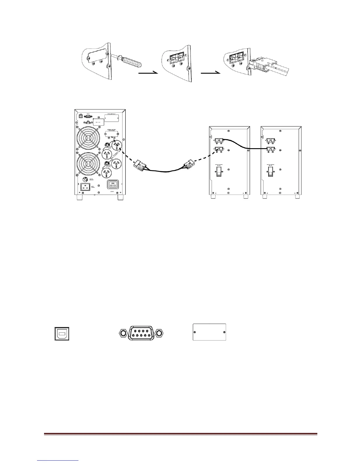
battery bank input connector.
2. Connect DC cable from the DC connector of UPS rear panel to the input DC
connector of Battery bank. Turn on battery circuit breaker of Battery banks.
NB : Battery banks can be used with both types of UPS’s. Although standard
battery banks can be used with Long run UPS’s usually these would have a
customised larger battery bank. Standard battery banks are used more commonly
with standard UPS’s to increase backup times
For installation of PSCEBB18CH. Please refer detail installation manual included in
the package of its product.
Step 4: Communication connection
Communication port:
USB port RS-232 port Intelligent slot
To allow for unattended UPS shutdown/start-up and status monitoring, connect the
communication cable one end to the USB/RS-232 port and the other to the communication
port of your PC. With the monitoring software installed, you can schedule UPS
shutdown/start-up and monitor UPS status through PC.
The UPS is equipped with intelligent slot perfect for SNMP or AS400 card. When installing
SNMP or AS400 card in the UPS, it will provide advanced communication and monitoring
options.
Note : AS400 and SMNP card cannot work at the same time.