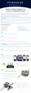
PQube 3 Installation Manual
Manual#: 851-000135
Version 3.4 – 08/11/2022 Page 13 of 47
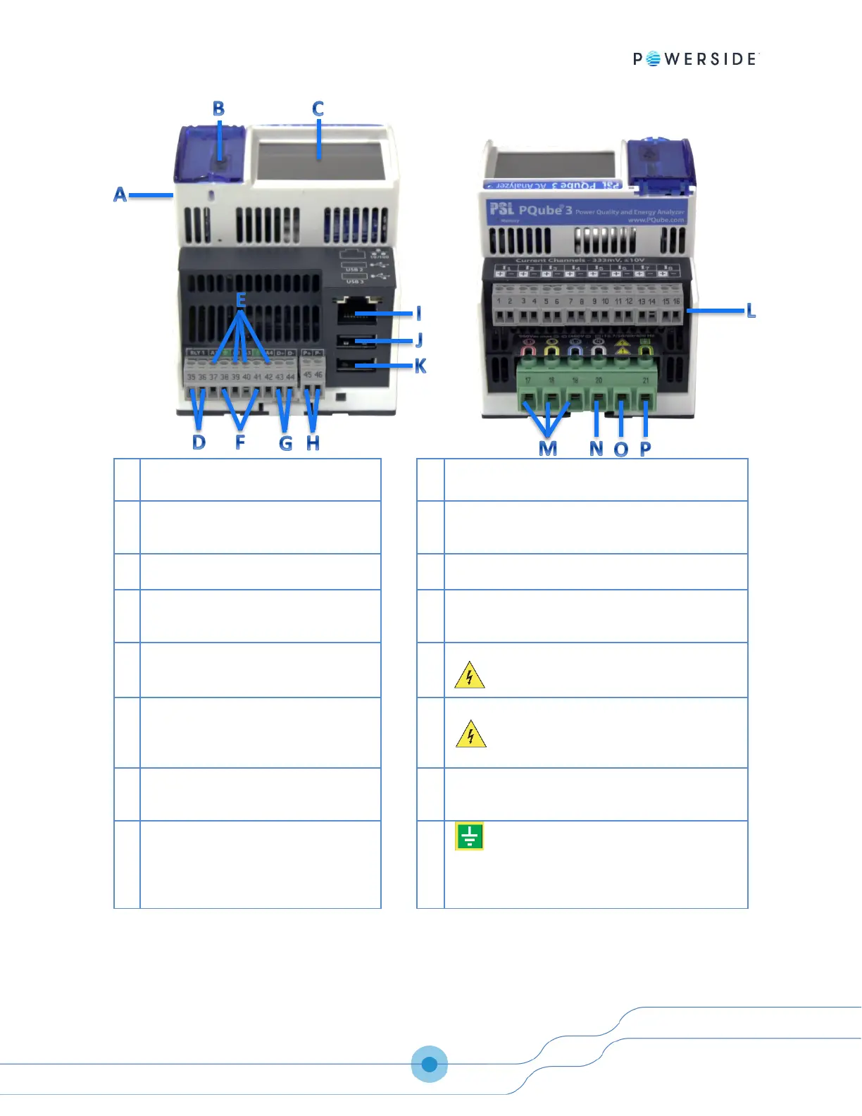
Coin-cell battery (keeps real time clock
alive when instrument power is lost)
10/100 Ethernet RJ-45 Port. 48V PoE compatible.
USB-1 High-Speed USB 2.0 Port for USB
hard drives and adjacent microSD card
slot (format using FAT32 file system)
USB-2 Standard USB 1.0 Port for use ONLY with ENV2
environmental probes.
USB-3 Standard USB 1.0 Port for use ONLY with ENV2
environmental probes.
Signal relay output. Normally closed
during recording mode. Opens ½ cycle
after the event or device shutdown.
Current transformer inputs—nominal 0.333V RMS
(LOW range) or ±10V
pk
(HIGH range)
Analog inputs. Maximum ±60 Vdc or 33
Vac to earth. Can be used as differential
inputs.
L1, L2, L3 voltage inputs. See page 29 for
maximum voltage ratings.
Earth—functional. Use as a reference
point for analog inputs (not needed if
using analog channels in differential
mode).
Neutral terminal—optional depending on
your power configuration
Digital input. Wetted with 2.4 V at 3
microamps. 1.5 V threshold. 60 V
maximum.
Not connected, for isolation from ground.
Power supply input. 24 Vac or 24 Vdc to
48 Vdc (either polarity) nominal. 20 VA
max
Earth—functional. Used as the reference
point for voltage measurements.
IMPORTANT: This terminal must be properly
connected to ground for safety, accuracy, and
reliability.
 Loading...