PQube 3 Installation Manual
Manual#: 851-000135
Version 3.4 – 08/11/2022 Page 24 of 47
2.2.6 Connecting the wires
Observe the wire size specifications and limitations. All conductors must be stranded copper. All
conductors and insulation systems and crimped devices must be appropriate for the application.
POWERSIDE recommends crimped ferrules on stranded wire. Tighten the screws on the high-voltage
terminal block to 0.5 newton-meters (4.4 inch-pounds) of torque. Observe all voltage ratings and
limits.
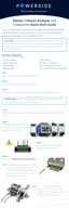
For connections, POWERSIDE recommends wire ferrules for stranded wire, such as Panduit F77 series, for
example Panduit F77-6-M.
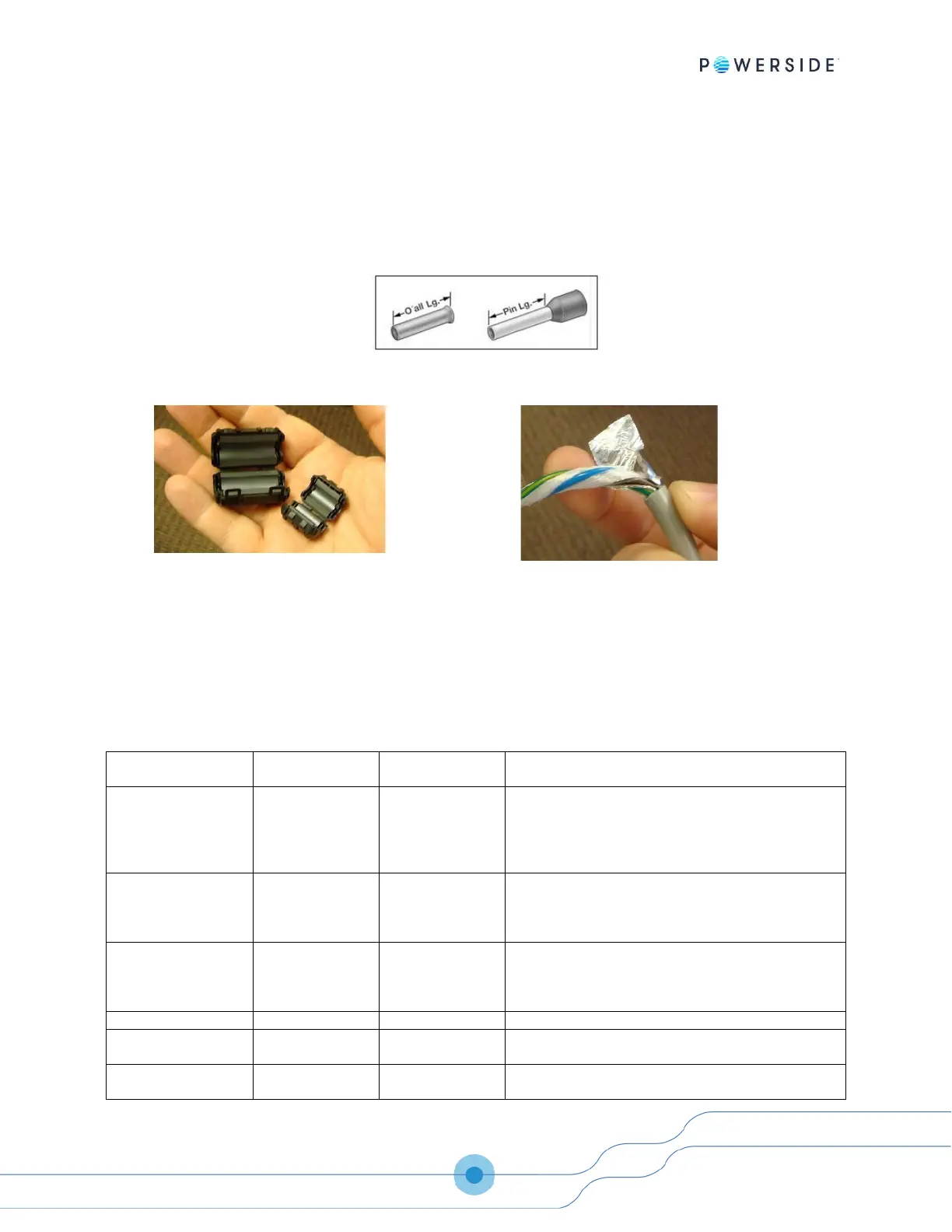
Your PQube 3 meets all IEC requirements for high-
frequency emissions and susceptibility, both
conducted and radiated. For further protection, you
can use clamp-on ferrites on signal cables to
minimize radio-frequency emissions. For example,
these are Panasonic KRCBC160928B and
KRCBC130714B.
To minimize emissions with the optional PM1/PM2
Power Supply module, optionally use a shielded
power conductor.
Conductor characteristics
Limitations and remarks. Comply with all local safety and
installation requirements and regulations.
PQube 3 terminals
L1, L2, L3, N
Minimum 600V UL-recognized insulation system required.
These terminals require less than 0.01 amps. Connection to
N (15) is optional. For single phase monitoring, connect
either L1-N or L1-L2 as appropriate for the mains
configuration.
Connect this terminal to a suitable earth connection. For
proper PQube 3 operation you must connect this terminal
to earth. It is used as a measurement reference, and as a
reference for your PQube 3’s low-voltage circuits.
Optional
PQube 3 terminals
Minimum 600V UL-recognized insulation system required.
Wire size must be adequate for relay contact load. These
terminals rated at 30 Vac max, 60 Vdc maximum, 2 amps
maximum.
Minimum 600V UL-recognized insulation system required.
Minimum 600V UL-recognized insulation system required.
Shielded cable recommended for minimizing emissions.
Minimum 600V UL-recognized insulation system required.
 Loading...