PQube 3 Installation Manual
Manual#: 851-000135
Version 3.4 – 08/11/2022 Page 33 of 47
2.2.14 For PQube 3r and PQube 3vr: Connecting the Output relays RLY2,
RLY3, RLY4
All PQube 3 have one relay RLY1 described in the section above.
However, the PQube 3r and PQube 3vr come with an additional 3 relays: RLY1, RLY2, RLY3.
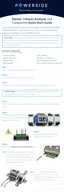
Each of those relays have a 3-pole terminal to connect the external logic circuit. They trip for at least 3
seconds or for the duration of the event whatever is longer.
Here is how to connect to a Normally Closed (NC) operation (here as an example for RLY2):
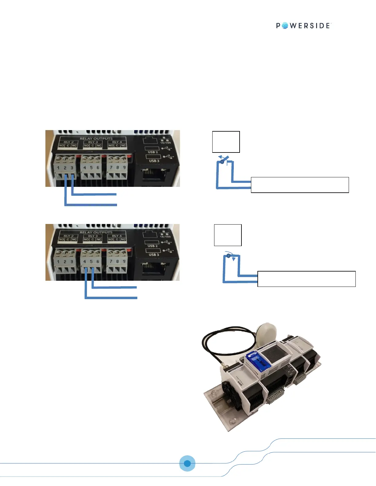
Here is how to connect to a Normally Open (NO) operation (here as an example for RLY3):
2.2.15 Installing GPS-R Sync Module (GPS Synchronization)
The optional GPS-R Sync Module connects to the left side
of your PQube 3; just plug it in. Connect the module
before supplying power to your PQube 3. The GPS-R Sync
Module interfaces with an OEM TNC type GPS antenna
using an RG58c/U cable.

 Loading...