PQube 3 Installation Manual
Manual#: 851-000135
Version 3.4 – 08/11/2022 Page 18 of 47
2 Installing the PQube 3
2.1 Unpacking the PQube 3
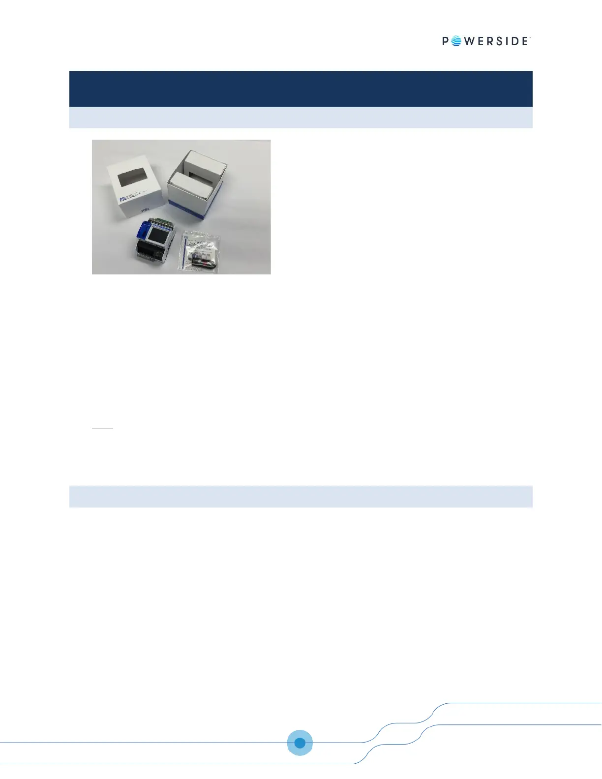
Verify that your package contents are complete:
➢ 1 PQube 3
➢ 1 USB thumb drive (contains the manual, quick-start guide, setup file, Configurator program,
and Report Writer program)
➢ 1 six-pole voltage connector (mains voltage)
➢ 8 two-pole connectors (current inputs)
➢ 1 two-pole connector (power supply)
➢ 1 ten-pole connector (for analog channels, digital input, relay output)
Note:
• PQube 3e comes with an additional 6 two-pole connectors (additional current inputs)
• PQube 3v, PQube 3vr do not have current terminals nor connectors
• PQube 3r and PQube 3vr come with a set of 3 three-pole connectors (for the additional 3 relays)
2.2 Installation
2.2.1 Disconnect mains prior to servicing
IMPORTANT: Your PQube 3 must be installed only by qualified personnel for electrical installations.
Always disconnect all mains connections, and verify disconnections, prior to servicing.
In the United States and Canada, the equipment installation shall meet ANSI/NFPA 70, NEC, with
CSA C22.1, CEC, Part I or with both as appropriate. In other countries, follow all local installation
requirements and regulations.
2.2.2 Mount your PQube 3 properly and securely
Your PQube 3, and its optional modules, are designed to be mounted on an industry standard 35
mm DIN rail as rack- or panel-mounted equipment.

 Loading...