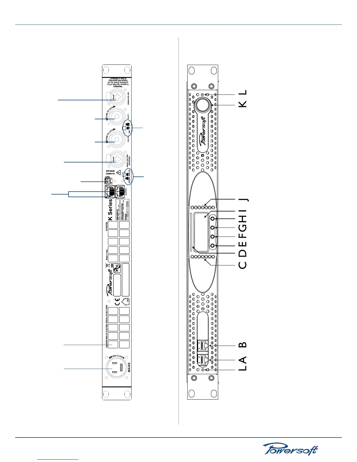
FIGURE 5: K6/K8/K10/K20 4-port version rear panel
Mains plug
Air vents
Ethernet +
AESOP ports
External
aux voltage
Channel 2 analog input or AES3
(depending on the position of the AES/EBU-
Analog button)
Channel 2
output
Channel 1
output
Channel 1 analog input
Channel 2 AES/EBU or analog
input selection button
Channel 1 and 2 output link
selection button
A - Ethernet port number 1
B - Ethernet port number 2
C - V meter for channel 1
D - SmartCard slot
E - Function button number 1
F - Function button number 2
G - Function button number 3
H - Function button number 4
I - LCD display
J - V meter for channel 2
K - On/Off switch
L - Grill filter screws
FIGURE 6: K Series detailed front panel view