to a strict minimum. Should however the amplier be subject to
an extreme thermal load, the fan will force a very large volume
of air through the heat sink. In the extremely rare event that the
amplier should dangerously overheat, sensing circuits shut down
all channels until the amplier cools down to a safe operating
temperature. Normal operation is resumed automatically without
the need for user intervention.
Caution regarding heat escape should be exercised when
mounting K Series ampliers. Exhaust cooling air is forced out
through the rear of the chassis (see FIGURE 8); make sure there
is enough space around the back of the amplier for this air to
escape. K Series ampliers can be stacked one on top of the other
due to the efcient cooling system they are equipped with. There
is however a safety limit to be observed: in case a rack with closed
back panels is used, leave one rack unit empty every four K Series
ampliers installed to guarantee adequate air ow.
FIGURE 8:
Air flow
Forced air cooling: front to back airow
4.4 Operating Precautions
Make sure the power switch is off before attempting to make any
input or output connections.
Make sure the AC mains voltage used is within the acceptable
operating voltage range specied in the K Series documentation
(100V-240V ±10%). Damage caused by connecting the amplier
to an improper AC mains voltage is not covered by the warranty.
By using good quality input and speaker cables, the likelihood of
erratic signal behavior is reduced to a minimum. Whether you
make them or buy them, look for good quality wires, connectors
and soldering techniques.
4.5 Grounding
There is no ground switch or terminal on the K Series ampliers.
All shield terminals of input connections are directly connected to
the chassis. This means that the unit’s signal grounding system is
automatic. In order to limit hum and/or interference entering the
signal path, use balanced input connections.
In the interests of safety, the unit MUST always operate with
electrical safety earth connected to the chassis via the dedicated
wire in the 3-wire cable. Never disconnect the ground pin on the
AC mains power cord.
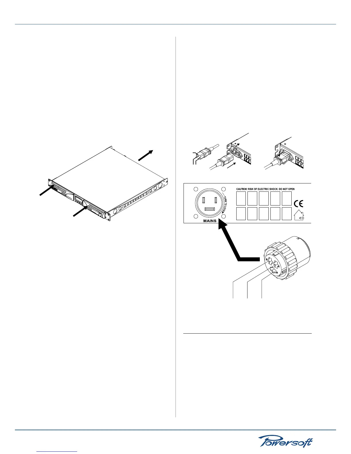
4.6 AC Mains connection
The AC Main connection is made via the CPC type connector
(IEC20A for K3 and K2) on the rear side of the panel. The
gure below shows how to connect the mains power cable to
the amplier. Make sure the AC mains voltage used is within
the acceptable operating voltage range specied in the K Series
documentation (100V-240V ±10%). It is important to connect the
ground for safety, do not use adapters that disable the ground
connection. All K Series ampliers have an automatic power
factor correction system for a perfect mains network interface.
The amplier is a resistive load for the mains network, minimizing
the reactive power and the harmonic distortion on the current.
The system allows performance to be maintained even in case of
varying mains voltage.
FIGURE 9:
ground
mains
open the lock
and insert the plug
lock the plug
K2 and K3 only mains connection
FIGURE 10:
K6/K8/K10/K20 mains connection
5 Connections and Operation
This chapter provides information on amplier connection and
operation. For optimal amplier performance, it is important
to understand the meaning of the information that the K Series
amplier can provide regarding its status and conguration. This
information is available to the user both via front panel indicators
or via the Armonía client software when this is used. This chapter
will break down all the front panel operations and monitoring
functions the K Series amplier is capable of. The remaining part
of the chapter will explain how to correctly connect the amplier’s
inputs and outputs.