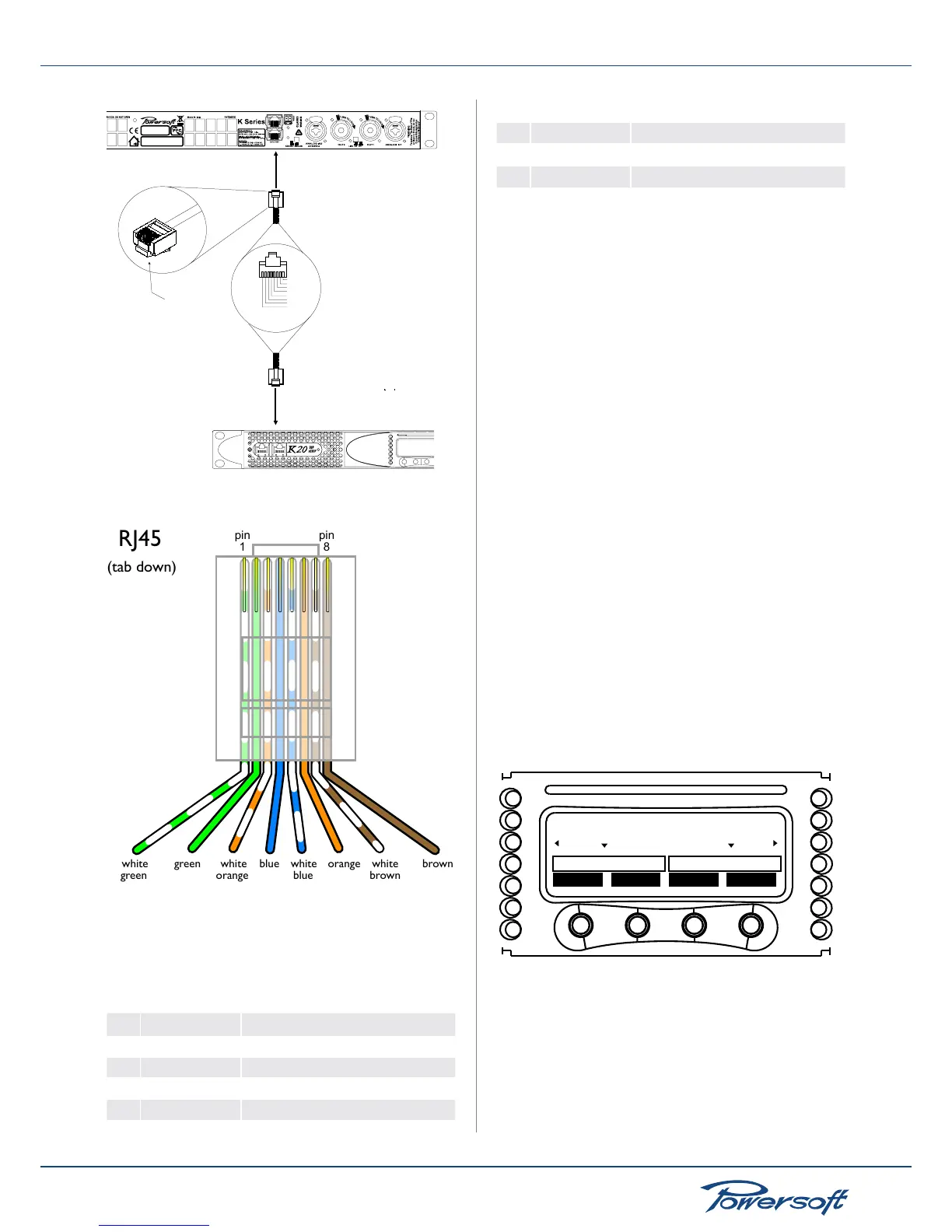
RJ45 jack pinout for KAESOP connections
The RJ45 LEDs are coded s follows:
green LED: indicates the passage of control data
yellow LED: indicates the passage of AES3 signals
Remote connection jack pinout chart:
pin color RJ45 KAESOP pin out
1 white/green 100BaseT AutoMDI RX/TX +
2 green 100BaseT AutoMDI RX/TX -
3 white/orange 100BaseT AutoMDI TX/RX +
4
blue
AES3-A RX/TX +
5
white/blue
AES3-A RX/TX -
6
orange
100BaseT AutoMDI TX/RX -
7
white/brown
AES3-B RX/TX +
8
brown
AES3-B RX/TX -
5.5 Amplier Setup and Settings
5.5.1 Introduction
In all K Series ampliers, the combination of the front panel
buttons together with the LCD display allow the user access to
detailed information and complete control over the amplier’s
status. Each button has multiple functions and the display
shows the current active function for each button. This chapter
illustrates all the functions and settings accessible via the
amplier front panel. FIGURE 6 illustrates all K Series front panel
elements.
Armonía Pro Audio Suite
All the setup and settings functions described in this section can be
accessed through a comptuer by installing Powersoft’s Armonía
Pro Audio Suite software. Armonía is a software environment
entirely developed in-house by Powersoft. Its two main features
are full end user remote control of the amp and its signal processing
capabilities. The intuitive interface provides reliable information
and real time control of all DSP functions (see “18.4.1 Powersoft’s
Armonía Pro Audio Suite” on page 45). Refer to the Armonía
manual for installation and conguration of the client software.
Armonía is free. It can be downloaded after signing up for our user
forum: see the “Armonía Support Forum” section at
http://www.powersoft-audio.com/
5.5.2 The main screen and the LED bars
When the amp is turned on, the main screen appears after a
short presentation.
lock
mute mute menu
CH1 READY READY CH2
V I VI
FIGURE 25: K Series main screen
The rst line of the screen will read “WAIT” while the system
undergoes an initial batch of internal tests to determine the status
of the amp. If all parameters are normal, “READY” will replace
“WAIT” on the display. System parameters are continuously
monitored by the internal controller. If any parameter value should
fall out of its correctly working range, a code error relative to that
particular parameter will appear on the third line of the LCD meter