7. Bandpass
8. Allpass
By pressing the “edit” button, the settings for the selected lter
can be changed. The following chart summarizes which parameters
can be edited according to the selected lter type.
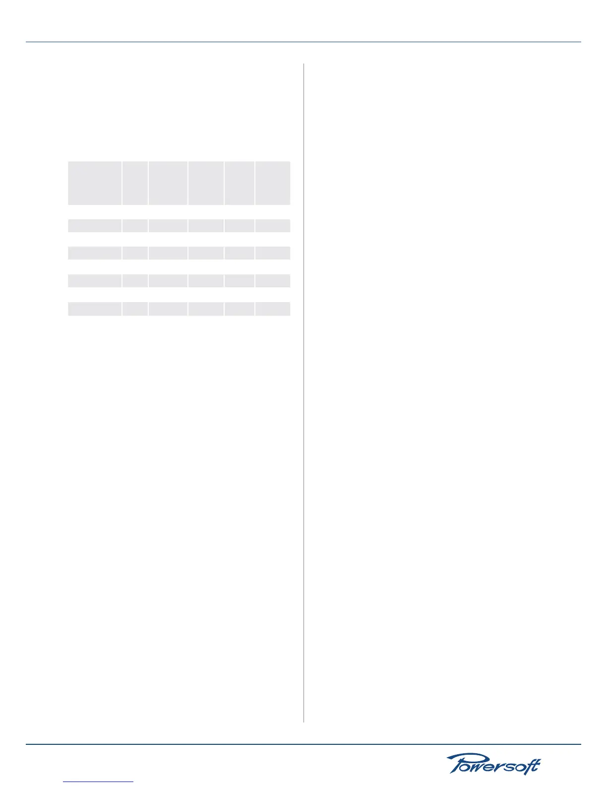
Parametric Equalizer (PEQ) settings according to lter type:
lter type
Active
on/off
Freq
(20-20kHz,
1/96 steps)
Gain
(-15 to
+15dB,
0.1dB
steps)
Slope
(3-15dB/
oct)
Q factor
(0.1-30,
0.1 steps)
Peaking
✓ ✓ ✓
-
✓
Low Shelving
✓ ✓ ✓ ✓
-
High Shelving
✓ ✓ ✓ ✓
-
Low pass EQ
✓ ✓
- -
✓
High pass EQ
✓ ✓
- -
✓
Bandstop
✓ ✓
- -
✓
Bandpass
✓ ✓ ✓
-
✓
Allpass
✓ ✓
- -
✓
8.2.2.2 LP Filter (and HP Filter)
This menu allows the user to congure the crossover lters.
There are 2 available crossover lters: a lowpass and a highpass.
By combining both, the result will be a bandpass response. Both
traditional IIRs (Innite Impulse Response) as well as brickwall
linear phase FIRs (Finite Impulse Response) are implemented. If a
FIR lter in the EQ section is enabled, a FIR crossover lter cannot
be enabled at the same time. The LP or HP lter can be edited
by the user via the main LCD screen. The parameters that can be
user modied are:
▶
active status
▶
frequency
▶
slope
▶
lter type
The classic IIR crossover lter shapes that can be selected as a high
pass or low pass lter are: Butterworth, Bessel, and Linkwitz-Riley.
In the rst 2 cases, the frequency parameter in the edit window
denes the –3dB point, in the latter, the –6dB point. The slope is
freely selectable from a minimum of 6dB/octave (1st order lter)
to 48dB/octave (8th order lter).
The FIR lters can be selected as normal (FIR Linear Phase) or
enhanced (Hybrid FIR). The enhanced version of the lters gives
a higher rejection of out of band signals, at the expense of a small
(30°@400Hz) phase modication. In both cases, the minimum
working frequency is relative to the desired latency. Standard
setting limit this to 400 Hz. For this reason it is advisable to use
FIR lters to crossover upper midranges or mid-high drivers for
which the phase coherency is a key point.
8.2.2.3 Polarity
This menu allows to reverse the signal polarity. The two selectable
modes are:
▶
In phase: the signal’s polarity is not altered
▶
Reversed: the signal’s polarity is reversed.
8.2.2.4 Channel Delay
This menu allows to set a single channel output delay. This is helpful
to time-align two different loudspeakers on the two amplier
channels. The selectable delay varies from 0 to 32 ms (about 11
meters), with a single sample step (equal to 1/96000th second or
10.4 us, about 3.5 mm)
8.2.2.5 Gain
This menu changes the channel gain, from –40dB to +15dB, with
a 0.1dB step.
8.2.2.6 Limiters
The limiting process in sound reinforcement is a way to protect
loudspeakers from accidental damage; therefore, limiters are a
safeguard against excessive signal peaks and/or signal power. They
not only protect from sudden signal peaks but also they protect
against to an over power delivering.
Bear in mind that limiting does not only prevent occasional
damage, but it rst and foremost guarantees a long component
life. The two main purposes of limiting process are:
▶
Over-excursion: an impulsive signal can reach the speakers
and cause damage due to over-excursion of the voice coil
that is driven out of the magnetic gap (where displacement
exceeds Xmax). This can damage the diaphragm (breaking or
deforming it).
▶
Over-heating: delivering high power to the voice coil may
lead to overheating of the voice coil copper and the relative
magnetic gap. This can damage the isolation copper or burn
out the copper. Another evident high power driving effect is
power compression, noticeable in low frequency speakers.
In order to prevent the two mentioned phenomena two kinds of
limiters are provided:
▶
Peak limiter: protects against mechanical damages. The
peak limiter may also be used to control amplier clipping.
Designers should set this limiter’s parameters as a function of
both the maximum displacement (Xmax) of the diaphragm as
well as the speaker’s maximum tolerated voltage.
▶
RMS limiter: protects speakers against thermal damage when
excessive power is applied for extended periods of time,
resulting in overheating and, eventually, burning. Designers
should be aware of the maximum long term power safely
applicable to speakers (AES power rating). An interesting
approach to RMS limiting is one that uses coil temperature
control. A complete knowledge of the driver’s limits allows to
keep the temperature level in a safe interval not only to avoid
damage but to maintain the speaker in a “linear” zone that
avoids power compression.
Peak Limiter
The peak limiter avoids potentially dangerous displacements of
the cone (an excursion larger that allowed). It acts by reducing
the amplier gain in order to reduce the measured output peak
voltage. Use the declared Peak power or twice the Program power
as a loudspeaker safe-zone output power. The peak limiter’s setting