UPS-Mounted Bypass Switch Installation
36
Powerware
®
9155 UPS (8–15 kVA) User’s Guide S 164201553 Rev D www.powerware.com
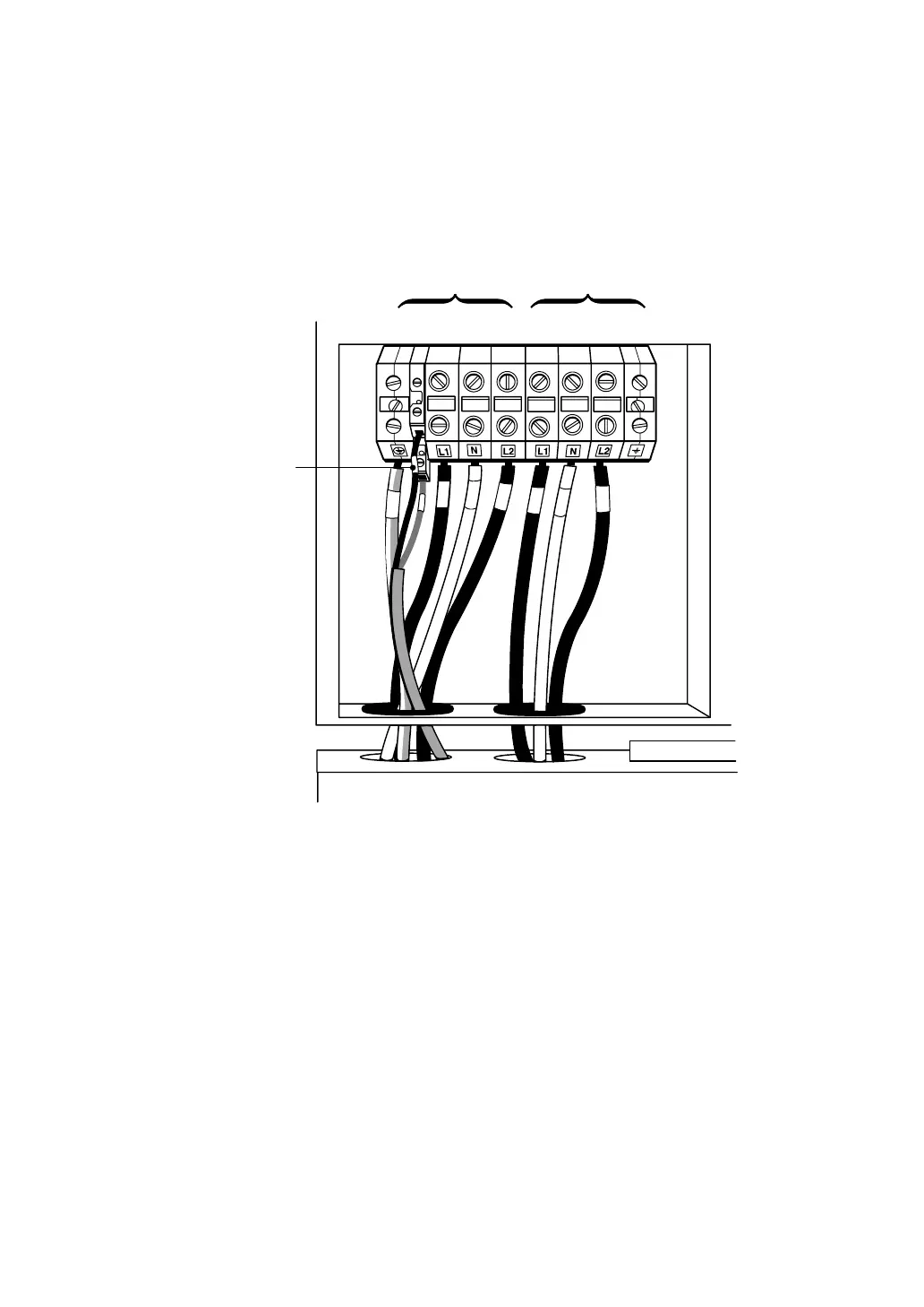
8. Connect the factory-installed wiring from the Maintenance
Bypass switch to the UPS terminal block (see Figure 19).
Connect the maintenance bypass (red and black) wires to TB1-2
(the A/B maintenance bypass auxiliary contacts) on the U PS
terminal block.
123 4 5 6 7 8 9
A/B Maintenance
Bypass Auxiliary
Contacts
TB1
Input
Output
Figure 19. Wiring from Maintenance Bypass Switch to UPS
9. Replace t he wiring access cover on the UPS and the optional
isolation transformer, if applicable.
10. Replace the MBM/PDM wiring access cover and conduit landing
plate.
11. Continue to “Stabilizing the Cabinet” on page 49 to complete
the installation.