Extended Battery Module Installation
52
Powerware
®
9155 UPS (8–15 kVA) User’s Guide S 164201553 Rev D www.powerware.com
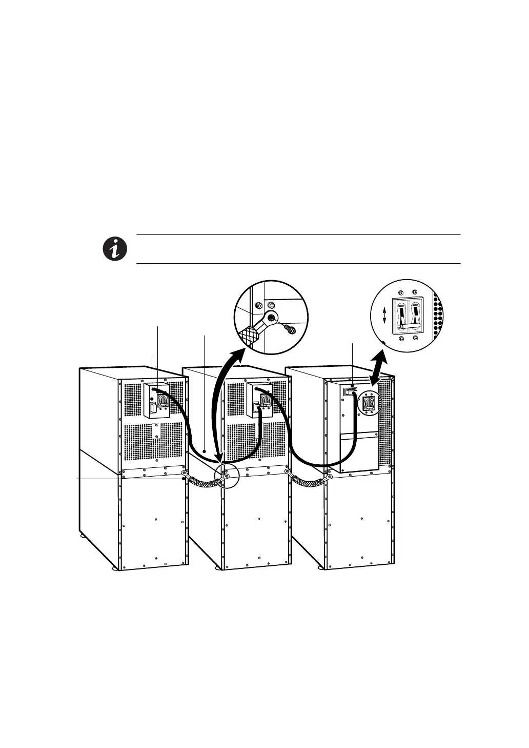
7. If additional EBMs are installed, plug the EBM cable of the
second cabinet into the battery connector on the first EBM.
Repeat for each additional EBM.
8. Attach a stabilizing bracket to each EBM if needed (see
“Stabilizing the Cabinet” on page 49).
9. Continue to one of the following sections:
쑺 “Communication” on page 53 to install UPS communication
options, such as X-Slot cards or REPO.
쑺 “Operation” on page 65 to start up the UPS.
NOTE After UPS startup, ensure maximum battery runtime b y
configuring the UPS for the correct number of EBMs (see page 75).
UPS Battery
Connector
Ground
Strap
EBM Battery
Circuit Breaker
EBM Battery Connector
EBM Cable
ON
OFF
UPS Battery
Circuit Breaker
Figure 31. Typical EBM Installation (2-High Cabinets Shown)