4116V105-UK 13
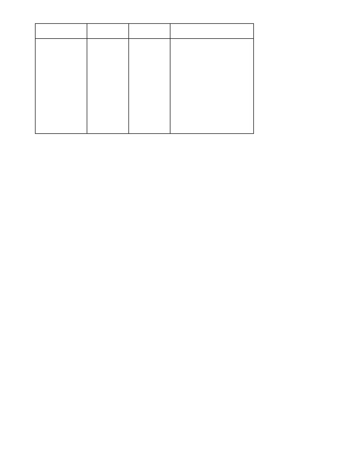
TC input
Type
Min.
value
Max.
value
Standard
B
E
J
K
L
N
R
S
T
U
W3
W5
LR
0°C
-100°C
-100°C
-180°C
-200°C
-180°C
-50°C
-50°C
-200°C
-200°C
0°C
0°C
-200°C
+1820°C
+1000°C
+1200°C
+1372°C
+900°C
+1300°C
+1760°C
+1760°C
+400°C
+600°C
+2300°C
+2300°C
+800°C
IEC 60584-1
IEC 60584-1
IEC 60584-1
IEC 60584-1
DIN 43710
IEC 60584-1
IEC 60584-1
IEC 60584-1
IEC 60584-1
DIN 43710
ASTM E988-90
ASTM E988-90
GOST 3044-84
Cold junction compensation (CJC):
via external sensor in connector 5910. . . . . . . . . . . . . . . . . . . . . . 20...28°C ≤ ±1°C
-20...20°C / 28...70°C ≤±2°C
via internal CJC sensor . . . . . . . . . . . . . . . . . . . . . . . . . . . . . . . ±(2.0°C + 0.4°C * Δt)
Δt = internal temperature - ambient temperature
Sensor error detection, all TC types. . . . . . . . . . . . . . . . . . . . . . . . . Yes
Sensor error current:
when detecting . . . . . . . . . . . . . . . . . . . . . . . . . . . . . . . . . . . Nom. 2 μA
else. . . . . . . . . . . . . . . . . . . . . . . . . . . . . . . . . . . . . . . . . . . 0 μA
Current input
Measurement range . . . . . . . . . . . . . . . . . . . . . . . . . . . . . . . . . . 0...23 mA
Programmable measurement ranges . . . . . . . . . . . . . . . . . . . . . . . . 0...20 and 4...20 mA
Input resistance . . . . . . . . . . . . . . . . . . . . . . . . . . . . . . . . . . . . Nom. 20 Ω + PTC 50 Ω
Sensor error detection:
Loop break 4...20 mA . . . . . . . . . . . . . . . . . . . . . . . . . . . . . . . . Yes
Voltage input
Measurement range . . . . . . . . . . . . . . . . . . . . . . . . . . . . . . . . . . 0...12 VDC
Programmable measurement ranges . . . . . . . . . . . . . . . . . . . . . . . . 0...1 / 0.2...1 / 0...5 / 1...5 / 0...10 and 2...10 VDC
Input resistance, nom.. . . . . . . . . . . . . . . . . . . . . . . . . . . . . . . . . 10 MΩ
Output specifications
Current output
Signal range (span) . . . . . . . . . . . . . . . . . . . . . . . . . . . . . . . . . . 0...23 mA
Programmable signal ranges . . . . . . . . . . . . . . . . . . . . . . . . . . . . . 0...20 / 4...20 / 20...0 and 20...4 mA
Load (max.) . . . . . . . . . . . . . . . . . . . . . . . . . . . . . . . . . . . . . . . ≤ 800 Ω
Load stability . . . . . . . . . . . . . . . . . . . . . . . . . . . . . . . . . . . . . . ≤ 0.01% of span / 100 Ω
Sensor error detection . . . . . . . . . . . . . . . . . . . . . . . . . . . . . . . . 0 / 3.5 / 23 mA / none
NAMUR NE 43 Upscale / Downscale . . . . . . . . . . . . . . . . . . . . . . . . 23 mA / 3.5 mA
Output limitation:
on 4...20 and 20...4 mA signals . . . . . . . . . . . . . . . . . . . . . . . . . . 3.8...20.5 mA
on 0...20 and 20...0 mA signals . . . . . . . . . . . . . . . . . . . . . . . . . . 0...20.5 mA
Current limit. . . . . . . . . . . . . . . . . . . . . . . . . . . . . . . . . . . . . . . ≤ 28 mA
Voltage output
Signal range. . . . . . . . . . . . . . . . . . . . . . . . . . . . . . . . . . . . . . . 0...10 VDC
Programmable signal ranges . . . . . . . . . . . . . . . . . . . . . . . . . . . . . 0...1 / 0.2...1 / 0...10 / 0...5 / 1...5 / 2...10 / 1...0 /
1...0.2 / 5...0 / 5...1 / 10...0 og 10...2 V
Load (min.) . . . . . . . . . . . . . . . . . . . . . . . . . . . . . . . . . . . . . . . 500 kΩ
of span = of the currently selected measurement range