EasyManua.ls Logo

PR 9113 - Routing Diagram

Default Icon
65 pages
Print Icon
To Next Page IconTo Next Page
To Previous Page IconTo Previous Page
Loading...
Power up
0000
PASSW.
Txt 1

12 mA
100@C
3
3
NO
ADV.SET
Txt 2
0000
9999
1 2
NO
YES
1 2
3
CURR
CH1 TYPE
Txt 3
CURR
TEMP
1 2
3
4-20
I.RANGE
Txt 4
4-20
0-20
1 2
3
YES
ADV.SET
Txt 2
3
23
OUT.ERR
Txt 13
1 2
4-20
O.RANGE
Txt 12
1 2
3
TEMP
CH1 TYPE
Txt 3
3
Pt
SENSOR
Txt 5
Pt
NI
TC
1 2
3
Ni
SENSOR
Txt 10
3
TC
SENSOR
Txt 10
3
100
Pt TYPE
Txt 16
1000
-
10
1 2
3
3W
CONNEC.
Txt 6
4W
3W
2W
1 2
100
Txt 17
1000
-
50
1 2
TC.K
TC.TYPE
Txt 18
TC.Lr TC.W5 TC.W3
TC.U TC.T TC.S TC.R
TC.N TC.L TC.WK
TC.J TC.E
1 2
3
3
3
3
3W
CONNEC.
Txt 6
4W
3W
2W
1 2
3
3W
CONNEC.
Txt 6
4W
3W
2W
1 2
3
INT
CJC
Txt 36
CONN
INT
1 2
3
1 2
@C
UNIT
Txt 9
@F
@C
1 2
3
20-4
20-0
4-20
0-20
23mA
0/3.5mA
NONE
1.2
1.1
1.0
3
Ni TYPE
Version No. V6R0 19
9113 TEMPERATURE / mA CONVERTER Safety Manual
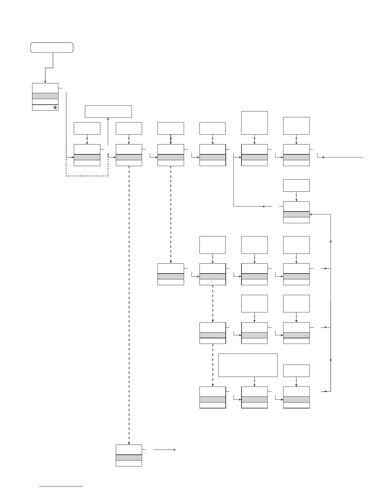
16.2 Routing diagram
1.0 = Default state. Line 1
shows input status,
line 2 and 3 show
analogue input /
output value or TAG
No. and units, and
line 4 shows status for
communication and
whether the device is
SIL-locked. Static dot
= SIL-locked and
flashing dot = not SIL-
locked.
1.1 = Only if password-
protected.
1.2 = Not valid for 0...20 mA
input signal.
1.3 = Only if input signal
is temperature.
Min. and max. acc. to
selected sensor type.
1.4 = Only if the configu-
ration is not protected
by a password.
Continued on the page
Routing diagram ADV.SET
If no key is activated for 1 minute, the display will return to the default state 1.0
without saving configuration changes.
1 Increase value / choose next parameter
2 Decrease value / choose previous parameter
3 Accept the chosen value and proceed to the next menu
Hold 3 Back to previous menu / return to menu 1.0 without saving
Red text signifies safety
parameters in a SIL
configuration.
If SIL-locked
directly to EN.SIL]

Table of Contents

Related product manuals