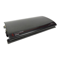
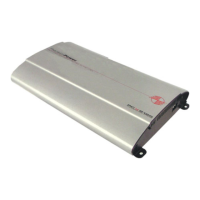
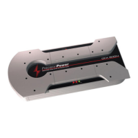
Do you have a question about the Precision Power PC2600 and is the answer not in the manual?
Do not attempt to service products yourself; performing exploratory surgery will void the warranty.
Extended use of high powered audio systems may result in hearing loss or damage. Observe all local sound ordinances.
Details technical specifications including power bandwidth, input sensitivity, impedance, and idle current.
Provides physical dimensions for PC2400, PC2600, and PC21400 models.
Chart detailing QBASS™ frequency centers and Q settings for bass boost.
Information about the optional dash-mounted remote boost control.
Details the QPORT™ expansion module for multi-amplifier control.
Lists required tools and parts for amplifier installation, not supplied with the unit.
Specifies maximum fuse ratings for PC2400, PC2600, and PC21400 amplifiers.
Guide to selecting minimum wire gauge based on current draw and wire length.
Fuse must be installed within 18" of battery to prevent fire hazard from shorts.
Instructions for proper amplifier grounding to bare metal for optimal performance.
Advice on upgrading charging systems for high current draw, and potential issues.
Step-by-step guide to connecting power and ground wires using the PowerLock connector.
Connects QBASS REMOTE™ and Power/Ground PowerLock.
Includes POWER indicator and QBASS™ Level control.
Locations of vents for the forced air cooling system.
RCA input jacks and -12dB attenuation switch for signal input.
Controls for adjusting input gain and selecting crossover modes.
Switches and buttons for configuring the QBASS PLUS™ circuit.
RCA outputs for sending processed audio signals to other amplifiers.
Diagram and instructions for connecting speaker wires and remote turn-on leads.
Explanation of bridging two-channel amplifiers for 4-ohm mono output.
Diagram showing RCA connection from head unit to amplifier inputs.
Caution regarding high powered/floating ground outputs and use of level adapters.
Explanation of circuitry that reduces noise by up to 40dB.
Details the built-in 90Hz Linkwitz-Riley crossover and HP/LP switch functionality.
Step-by-step guide for setting amplifier input gain to minimize noise and distortion.
Description of the heatsink design and requirement for 2" clearance.
Explanation of the thermally controlled fan for PC2600 and PC21400 models.
Diagnostic steps for when there is no sound output from the amplifier.
Steps to diagnose and resolve sound issues in only one channel.
Explanation of why the amplifier turns down (protection circuitry) and how to fix it.
How to run stereo speakers and a mono subwoofer simultaneously.
Diagram showing amplifier setup for high pass output to speakers.
Diagram showing amplifier setup for low pass output to subwoofers.
Setup with preamp/equalizer and phase control for high pass speakers.
Setup with preamp/equalizer and phase control for low pass subwoofers.
Diagram showing multiple amplifiers with crossover off for different frequency bands.
Illustrates -12dB attenuation and HP/LP/XOVER ON/OFF switch functions.
Shows QBASS PLUS™ and gain controls in the signal path.
Diagram of amplifier output stages and RCA output connections.
Chart and explanation of the variable detented crossover frequency adjustments.
Warranty terms for products installed by authorized dealers (3 years).
Warranty terms for products installed by non-authorized dealers (1 year parts, 90 days labor).
Conditions under which the warranty does not apply (serial number, misuse, etc.).
| Brand | Precision Power |
|---|---|
| Model | PC2600 |
| Category | Car Amplifier |
| Language | English |


 Loading...