18
2.7 Connections and Interfaces
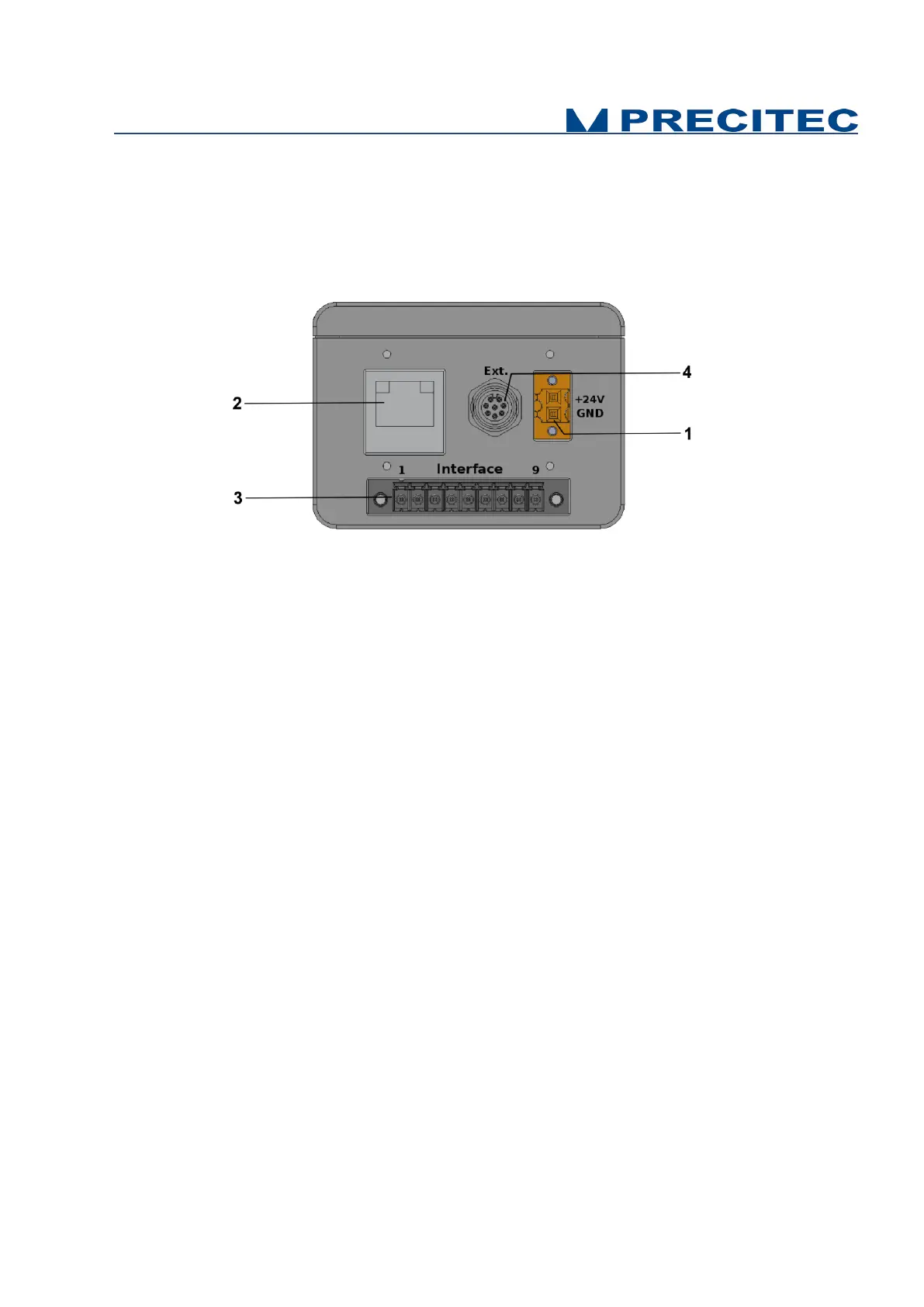
All of the connection ports for the sensor unit are located at the rear of the system (see Fig 2-7):
1. Power supply jack,
2. Ethernet interface, RJ45 port
3. 9-PINS Multipoint interface connector (Trigger / Serial communication)
4. 8-PINS round connector (analog converter module connection)
Fig. 2-7: CHRocodile C rear panel: Connections
2.7.1 Power supply jack
The CHRocodile C has two pluggable screw terminal for power supply with 24V
DC
+/-10%.
Connect the set of power cable supply associated to the Power Supply Adapter (100-240VAC to
24V
DC
+/-10%) delivered with the CHRocodile C unit.
2.7.2 Ethernet connector
The CHRocodile C has a RJ45 standard connector for Ethernet communication.
Connect the isolated RJ45 standard connector from the CHRocodile C unit to an Ethernet network
(PC). Ethernet supports the data transfer and can also be used for setting configuration by using $
command protocol (Cf. command SODX in Appendix 1), or for loading Calibration Table (Cf. command
TABL in Appendix 1). Ethernet communication allows to transmit a maximum of 16 data values at 4
KHz.
2.7.3 Trigger Input/Output and RS422 serial communication
The Trigger input/output use a multipoint connector interface (9 pins). This connector is used for
trigger Input / Output and for RS422 serial communication (Cf. Table 2-2 and Table 2-3).
The trigger options make the lighting cycle externally controllable and the synchronization between
e.g. a scanning system cycle and the CHRocodile C measurement rate. This means that external
triggering is possible for every measurement up to the full measurement rate of 4000Hz.