34
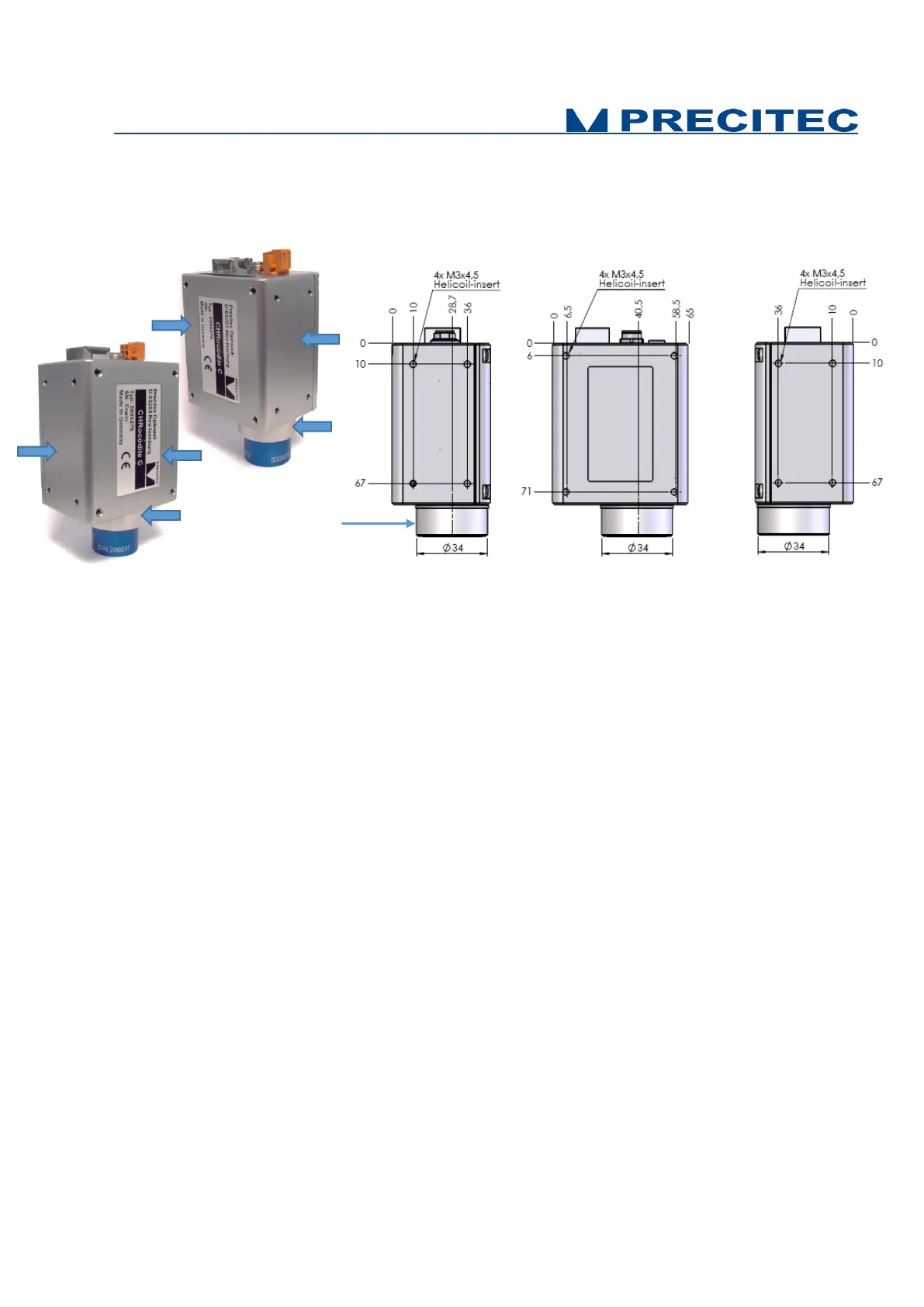
Fig 4-3: CHRocodile C unit mechanical interface: fixture holes on:
a- lateral surface 1
b- soleplate,
c- lateral surface 2.
4.4 Basic Settings Configuration
In order the CHRocodile C to be operational for startup some basic parameters should be set up. You
can also refer to the CHRocodile C quick start guide documentation.
Basic setting configuration consists in selection of:
• Measuring Range: The CHRocodile C could accept up to 8 calibration tables. Each calibration
table corresponds to a unique optical probe. Consequently, depending on the optical probe
which is mounted on the CHRocodile C unit, the operator must select the right measuring
range or calibration table. (Cf. command $SEN in Appendix 1)
• Data transmission: The CHRocodile C can transmit different data: up to 4 Altitudes, up to 4
Intensities and up to 3 Thicknesses. Depending on the application, operator must select the
right data. (Cf. command $SODX in Appendix 1)
• LED intensity level: The LED intensity Level can be adjusted from 0 to 100%. As for
measuring rate, this adjustment essentially depends on object reflectivity. Adjust LED intensity
in order to obtain a high signal intensity, but avoid saturating the detector (intensity LED blinks
orange). In order to adjust LED intensity, use the LAI command (Cf. Appendix 1).
Possible fixture on
the surrounding ring.