Installing the Console 49
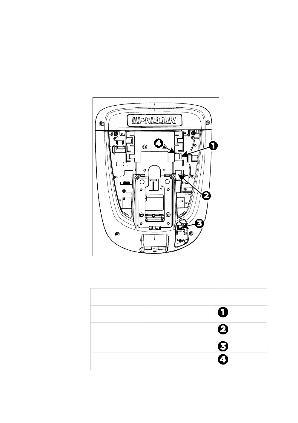
After the console has been seated, separate the individual
cables out of the end of the console cable assembly and
attach them to the appropriate circuit connectors inside the
console. Refer to the following diagram and table to identify
the cables and connectors.
Important: All cables must pass through the opening in the
center of the console mount.
Figure 28: Cable connections, P30 and P10 consoles
Table 3. P30 and P10 internal cable connections
Cable Connector Type Circuit Connector
Location
Safety key (treadmills
only)
Six-contact strip, keyed
Data from base unit Eight-contact modular,
on flat gray cable
Heart rate sensors Four-contact strip, keyed
CSAFE Eight-contact modular,
on flat gray cable

 Loading...