128-9316
4 of 16
Page 4
MOUNTING OF THE MAJOR COMPONENTS
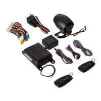
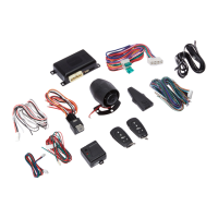
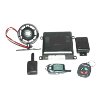
Control Module: Part # 1365410
Select a mounting location inside the passenger compartment ( up behind the dash ), and secure using
the two screws provided. The control module can also be secured in place using cable ties.
NOTE: Do not mount the control module in the engine compartment, as it is not waterproof. You should also
avoid mounting the unit directly onto factory installed electronic components. These components
may cause RF interference, which can result in poor transmitter range or intermittent operation.
Siren: Part # AS9903E
Select a mounting location in the engine compartment that is well protected from access below the vehi-
cle. Avoid areas near high heat components or moving parts within the engine compartment. To prevent
water retention, the ared end of the siren must be pointed downward when mounted.
Mount the siren to the selected location using the screws and bracket provided.
Hood or Trunk Pin Switch: (Optional) Part #1363699
An optional pin switch should be used for protecting the hood or trunk (or hatchback ) of the vehicle. The
switch must always be mounted to a grounded, metal surface of the vehicle. It is important to select a
location where water cannot ow or collect, and to avoid all drip gutters on hood and trunk fender walls.
Choose locations that are protected by rubber gaskets when the hood or trunk lid is closed. The pin
switch can be mounted using an optional bracket or can be directly mounted by drilling a ¼" diameter
mounting hole. Keep in mind that when properly mounted, the plunger of the pin switch should depress
at least ¼" when the hood or trunk lid is closed.
Push-Button Program Switch/LED/Receiver/Antenna Assembly: PART # 1181255
The Superheterodyne Receiver Antenna Assembly provided with this unit allows routing from below the
dash board for maximum operating range. Choose a location above the belt line (dashboard) of the
vehicle for best reception. Special considerations must be made for windshield glass as some newer
vehicles utilize a metallic shielded window glass that will inhibit or restrict RF reception. In these vehicles,
route the antenna toward a rear window location for best reception. Secure the antenna with double
stick tape provided.
Shock Sensor: Part # AS9492a
Select a solid mounting surface for the shock sensor on the rewall inside the passenger compartment,
and mount the sensor using the two screws provided. The shock sensor can also be secured to any xed
brace behind the dash using tie straps.
Whichever mounting method is selected, make certain that the sensitivity adjustment is accessible for
use later in the installation.
STARTER INHIBIT RELAY: Part # 1363731
Select a mounting location within 12" of the ignition switch's low current start solenoid wire. Secure the relay to an
existing harness in the chosen location using a cable tie around the relay's wiring harness.
Wire the relay as per the diagram found later in this manual.
CAUTION! Do not wire tie the metal bracket to an existing wiring harness as vibration may cause
chafng and shorting damaging the factory wiring. If an existing harness is not available
then secure the relay's metal mounting tab to an under dash metal brace with a #8 self
tapping sheet metal screw. Wire the relay as per the diagram found later in this manual.

 Loading...