128-9316
5 of 16
Page 5
WIRING THE SYSTEM
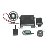
6 Pin Power Connector: P/N 1124297
Red/White (5 Amp) And Red Fused (15 Amp) Wires : + 12 VDC Constant Battery Source
This wire supplies power to the alarm's control module as well as the input to the parking light relay.
Connect this input to a constantly on + 12 volt supply.
Orange Wire: 300 mA Ground Output When Armed
This wire is provided to control the starter cut relay. Connect the orange wire to terminal 86 of the relay.
Connect relay terminal 85 to an ignition wire in the vehicle that is live when the key is in the on and crank
positions and off when the key is in the off position. (This is where the yellow wire from the alarm should
be connected).
Cut the low current starter solenoid wire in the vehicle, and connect one side of the cut wire to relay
terminal 87A. Connect the other side of the cut wire to relay terminal 30.
NOTE: This is a normally closed starter cut arrangement and when power is removed from the security
system, the starter disable feature will not operate, allowing the vehicle to start. Audiovox does
not recommend using the Orange wire to interrupt anything but the starting circuit of the vehicle.
Black Wire: Chassis Ground
Connect this wire to a solid, metal part of the vehicle’s chassis. Do not confuse this wire with the thin
black antenna wire that exits the control module independently.
White w/ Black Trace Wire: Positive Output to Siren
Route this wire through a rubber grommet in the rewall, and to the siren location.
Connect the white / black wire to the positive wire of the siren. Secure the black ground wire of the siren
to chassis ground.
Red Wire: + 12 Volts Module Supply
See Red/White Above.
White Wire: + 12 VDC Pulsed Parking Light Output (15 Amp Max)
This wire is provided to ash the vehicle’s parking lights. Connect the white wire to the positive side of
one of the vehicle’s parking lights.
14 Pin Main Wiring Harness P/N 1124303
1 Black w/ White Trace Wire: 300 mA Horn Output
The black w/white trace wire is provided to beep the vehicle’s horn. This is a transistorized low current
output, and should only be connected to the low current ground output from the vehicle’s horn switch.
If the vehicle uses a + 12 VDC horn switch, then connect the black w/ white trace wire to terminal 86 of
the AS 9256 relay ( or an equivalent 30 Amp automotive relay ), and connect relay terminal 85 to a fused
+ 12 VDC battery source. Connect relay terminal 87 to the vehicle’s horn switch output, and connect
relay terminal 30 to a fused + 12 VDC battery source.

 Loading...