128-9351
16 of 16
Page 16
© 2014 Voxx Electronics Corporation, 150 Marcus Blvd. Hauppauge, NY 11788 128-9351
For technical support go to www.prestigecarsecurity.com or call 1 800 225 6074
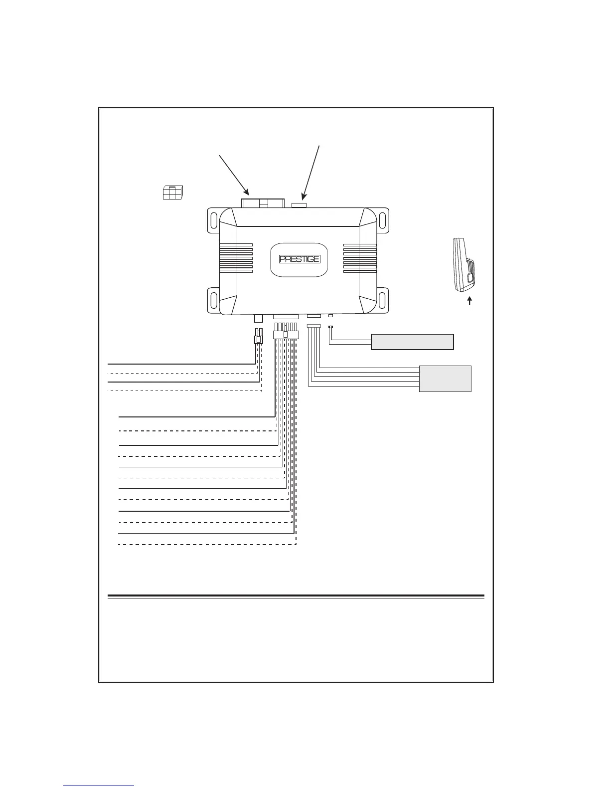
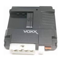
APS622E
Wire Side View Of Connector
1 Blue (Ign 1)
2 Red/White (+ 12VDC Relays Ign 1 & Ign 2)
3 Green (Ign 2)
4 Purple (Accessory)
5 Red (+ 12VDC Relays ACC & Start)
6 Yellow (Starter)
Connect Data Module
DBI Protocol
To Mating Connector
Push Button
LED Transceiver
500mA
MAX
(-) Lock Output
(-) Unlock Output
Green
Red
Yellow/Black (To controlling Alarm’s Ign Input)
White (Parking Light Relay Output)
Black (Chassis Ground)
White/Red (Parking Light Relay Input)
123
456
1 Green/Orange Tach Input
3 Black/Blue (-) Pulse Before Start Output
4 Black/LT.Green (-) Pulse After Start Output
5 LT. Blue Ground Out While Running
7 Green/Yellow Glow Plug Input
8 Brown (+) Inhibit Wire Brake Input
9 Gray (-) Negative Inhibit Wire Hood Pin
10 Black/Red (-) Pulse After Shut Down Output
11 Black/Yellow (-)Pulse During Crank Output
2 Empty Cavity No Connection
6 DK. Blue (-) Trunk Release Output
12 Black/White (-) Horn Output
Blue (LED -)
Grey (Valet)
Black (-)
Green (RX)
Red (+)