128-9351
6 of 16
Page 6
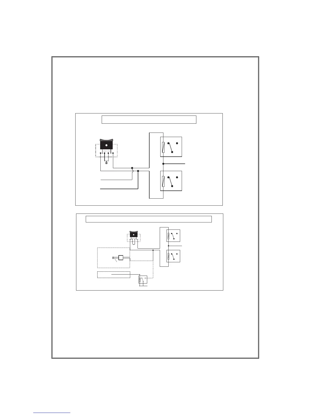
Factory Lock Relay
Factory Unlock Relay
87a 87
30
85
86
87a 87
30
86
85
From Fuse Box + 12 Volts
LockUnlock
To Red Lock Wire
Of Control Module
To Green Unlock Wire
Of Control Module
rated 250mA output of the units door unlock/lock circuits. Plug the 2 pin connector of the
door unlock harness into the mating connector shell of the control module. Determine
the door lock and unlock circuit of the vehicle you are working on and wire according
to the diagrams shown.
3 Wire Negative Switched Door Lock Circuits:
In this application, The Green wire of the 2 pin harness provides a negative pulse
during the unlocking sequence. Connect the Green wire to the low current negative
signal wire from the factory door unlock switch to the factory door unlock relay.
Factory Lock Relay
Factory Unlock Relay
87a 87
30
85
86
87a 87
30
86
85
LockUnlock
When Using DLVI
X
Cut and Splice
Per the Install
Guide Instruction
Blue
When Using Relays
Factory Unlock Relay
87a 87
30
85
86
To Fused + 12 Volts
(+)
From Vehicle
Chassis Ground
Green NC
To Green Unlock Wire
Or PBS Wire Of Control Module
To Green Unlock Wire
Or PBS Wire Of Control Module
Positive Type Door Lock Circuits
Negative Type Door Lock Circuits
NOTE: Resistive Circuits, Multiplex Circuits As Well As 4 Wire Polarity Reversal
and 5 Wire Alternating 12 Volt Door Lock Control Circuits
These applications require the use of additional components which may include relays,
xed resistor, a door lock interface, or a data module. You can search the vehicle @
www.Flash-It.com for vehcile specic information, or contact our tech service line or
web site for additional information.